Roll compensation system for rail vehicles
a compensation system and rail vehicle technology, applied in the direction of bogies, railway components, transportation and packaging, etc., can solve the problems of high design cost, high manufacturing cost, high cost of sensor technology and maintenance,
- Summary
- Abstract
- Description
- Claims
- Application Information
AI Technical Summary
Benefits of technology
Problems solved by technology
Method used
Image
Examples
first embodiment
[0034]Different conceivable embodiments of the invention are explained in greater detail with reference to the further figures. These embodiments differ in particular by virtue of the position of the car body in the default setting. FIG. 3 schematically shows a hydraulic circuit diagram in a first embodiment, the so-called “default setting down variant”.
[0035]All descriptions and performance data relate to a bogie. The decision whether certain components (e.g. oil container and pump) should be embodied centrally for each car body or for each bogie is made during the project implementation.
[0036]This first embodiment advantageously requires no displacement sensors; the positional displacement of the serial hydraulic cylinders is mechanically defined by permanent stops and is achieved purely by pressurization and monitored by means of pressure sensors.
[0037]The everyday operation is defined by the following functionality:
[0038]1) Zero-current state: all valves (DRV, displacement valve...
second embodiment
[0046]FIG. 4 schematically shows a hydraulic circuit diagram in a second embodiment, the so-called “default setting midway variant with displacement measurement system”.
[0047]This embodiment advantageously allows the geometry of the swing guide to be used for the radial adjustment of the wheelset, thereby minimizing the wheel wear.
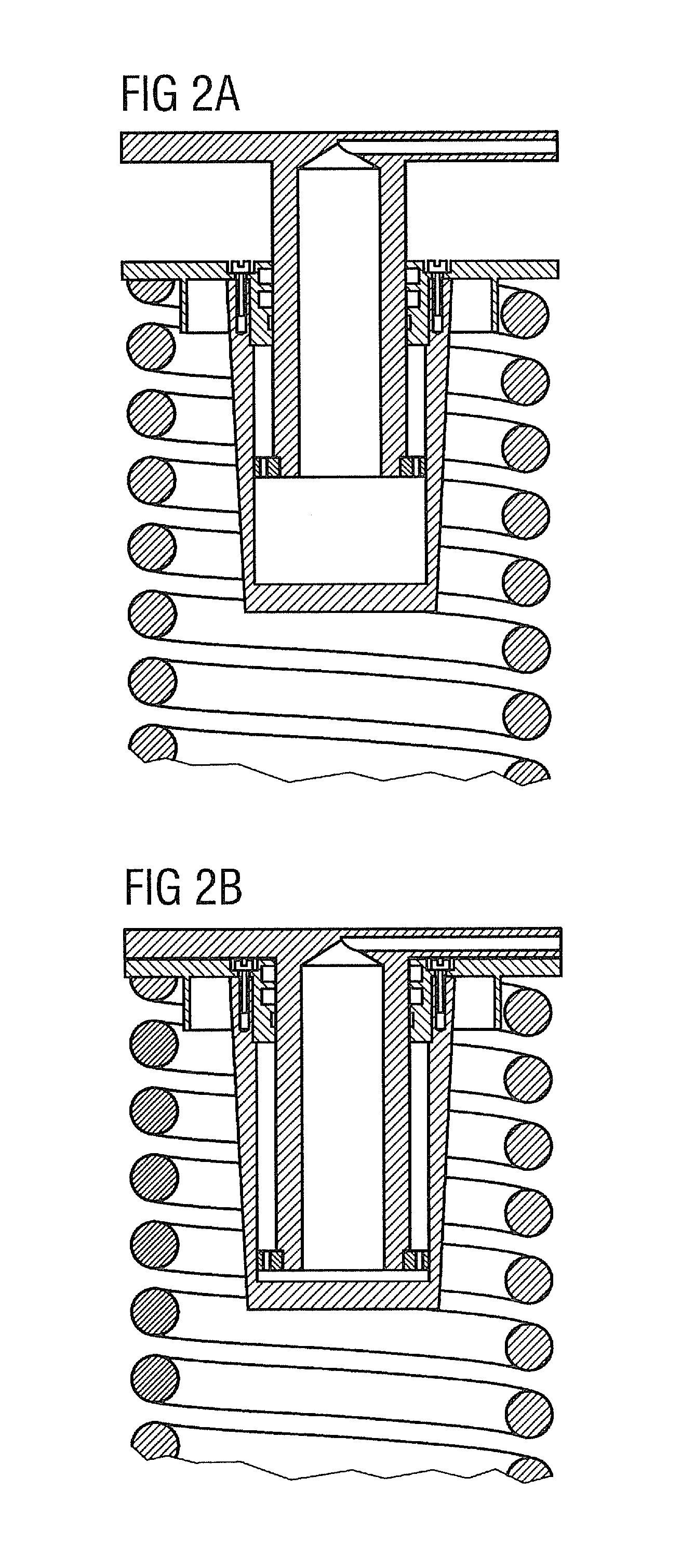
[0048]As illustrated in FIG. 4a, the actuator is arranged in series with the primary spring, and the displacement measurement system (4 per bogie) is protectively housed in the actuator (measures the actuator displacement without the spring displacement of the primary spring).
[0049]The everyday operation is defined by the following functionalities:
[0050]1) Zero-current state: all valves (DRV, displacement valve, discharge valve) are fully open, the system including high-pressure store is pressureless. The car body has its lowest (fail safe) setting.
[0051]2) In the presence of current and an electrical signal from the control unit, the pressure discharge va...
third embodiment
[0060]FIG. 5 schematically shows a hydraulic circuit diagram in a third embodiment, the so-called “default setting midway variant with auxiliary piston”. The structural layout of the actuator with auxiliary piston is shown in FIG. 5a.
[0061]This embodiment advantageously allows the geometry of the swing guide to be used for the radial adjustment of the wheelset, thereby minimizing the wheel wear.
[0062]However, the adjustment of the default setting does not require displacement sensors, and instead the height is established by means of a telescopic actuator and a suitable choice of the piston surfaces (of main and auxiliary pistons) and control pressure. As a result of the larger surface of the auxiliary piston, the oil requirement and hence the high-pressure store are also larger.
ABBREVIATIONS
[0063]p0 pressureless for fully retracted cylinder (0 bar)[0064]p1 control pressure for midway setting (approximately 80 bar)[0065]p2 maximum pressure for fully extended actuator (approximately...
PUM
 Abstract
Description
Claims
Application Information
 - R&D
- Intellectual Property
- Life Sciences
- Materials
- Tech Scout
- Unparalleled Data Quality
- Higher Quality Content
- 60% Fewer Hallucinations
Browse by: Latest US Patents, China's latest patents, Technical Efficacy Thesaurus, Application Domain, Technology Topic, Popular Technical Reports.
© 2025 PatSnap. All rights reserved.Legal|Privacy policy|Modern Slavery Act Transparency Statement|Sitemap|About US| Contact US: help@patsnap.com


