Method for manufacturing a functional laminate, functional laminate and its use for security documents

a functional laminate and functional technology, applied in the field of manufacturing functional laminates and functional laminates, can solve the problems of shrinkage of plastic materials, damage to functional components, and destruction of plastic materials around functional components, and achieve the reduction of width, cracks or warping, and the risk of failure of functional components. , the effect of reducing the risk of cracking or warping

Inactive Publication Date: 2012-02-16
HID GLOBAL GMBH
View PDF7 Cites 3 Cited by
  • Summary
  • Abstract
  • Description
  • Claims
  • Application Information

AI Technical Summary

Benefits of technology

[0016]laminating the inlay with at least one additional layer in such a manner that the width of said recess or recesses is (are) considerably reduced or said recess or recesses is (are) substantially closed at least by surrounding material after lamination by virtue of shrinking of the functional laminate.
[0017]Accordingly, in a functional laminate manufactured by the method according to the invention, mechanical tensions due to heat induced shrinking of the substrate sheet or the at least one additional layer (at least in an xy-level of the functional laminate) are reduced or removed by the recesses that are substantially closed or whose width is considerably reduced after lamination. Hence, the functional component and its contact areas, if applicable, are not sub

Problems solved by technology

When the layers are laminated using heat and/or pressure, the macromolecules of the plastic material tend to shorten thus causing the plastic material to shrink.
Since the chip module itself does not shrink, the material is subjected to mechanical stress eventually leading to deforming, cracking or delaminating the material or at least residual stress which can result in damage to the functional components and their contacting with conductors, wires or antenna l

Method used


Image

  • Method for manufacturing a functional laminate, functional laminate and its use for security documents
  • Method for manufacturing a functional laminate, functional laminate and its use for security documents
  • Method for manufacturing a functional laminate, functional laminate and its use for security documents

Examples


Embodiment Construction

[0033]The present invention will become more fully understood from the detailed description given herein below and the accompanying drawings which are given by way of illustration only, and thus, are not limitative of the present invention, and wherein:

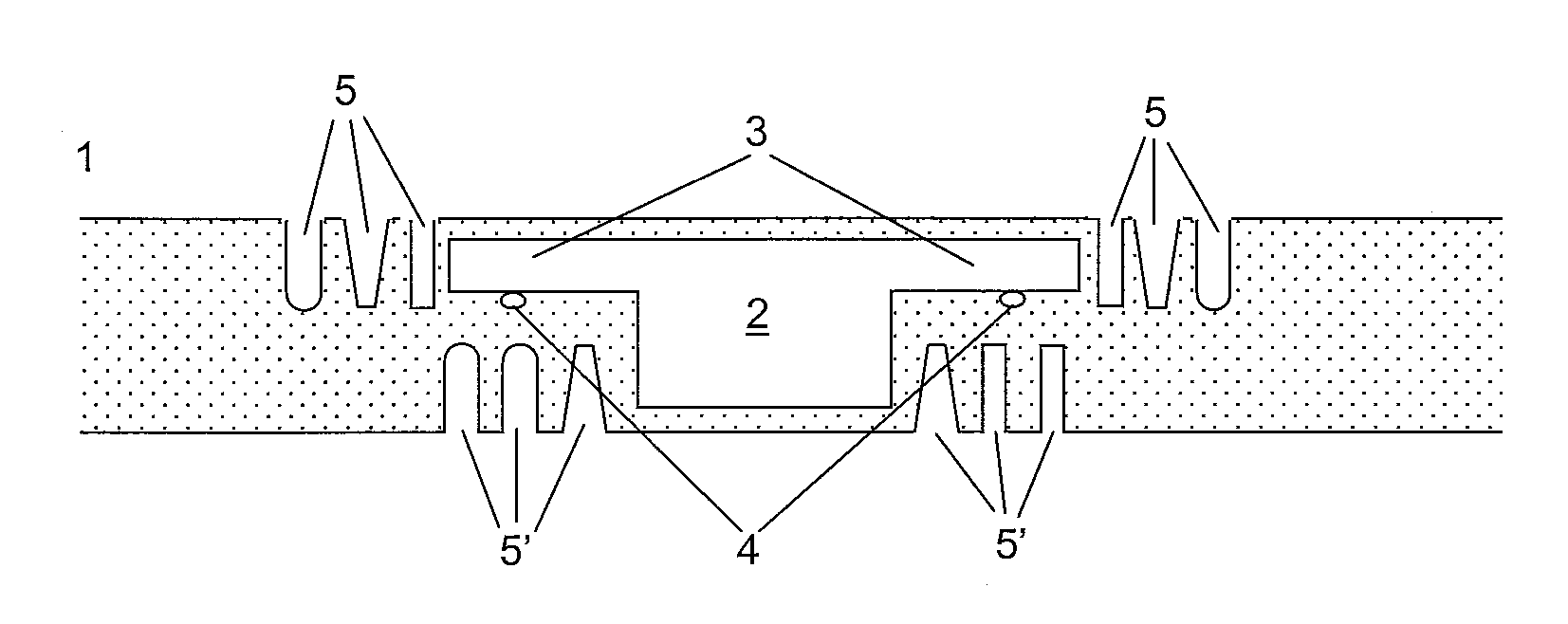
[0034]FIG. 1 is a sectional view of a inlay with an embedded functional component,

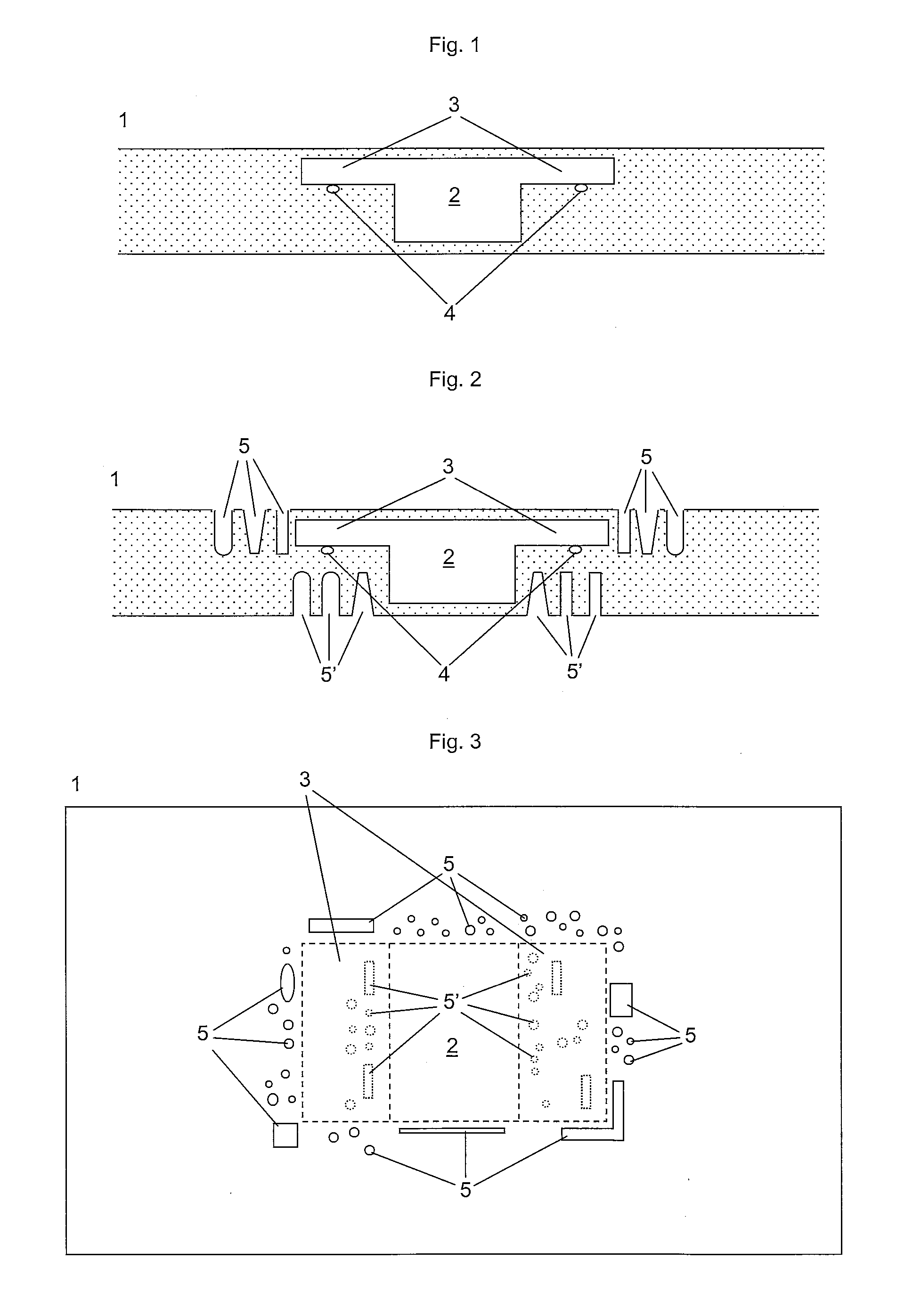
[0035]FIG. 2 is a sectional view of a inlay with a plurality of recesses around the functional component

[0036]FIG. 3 is a top view of the inlay of FIG. 2

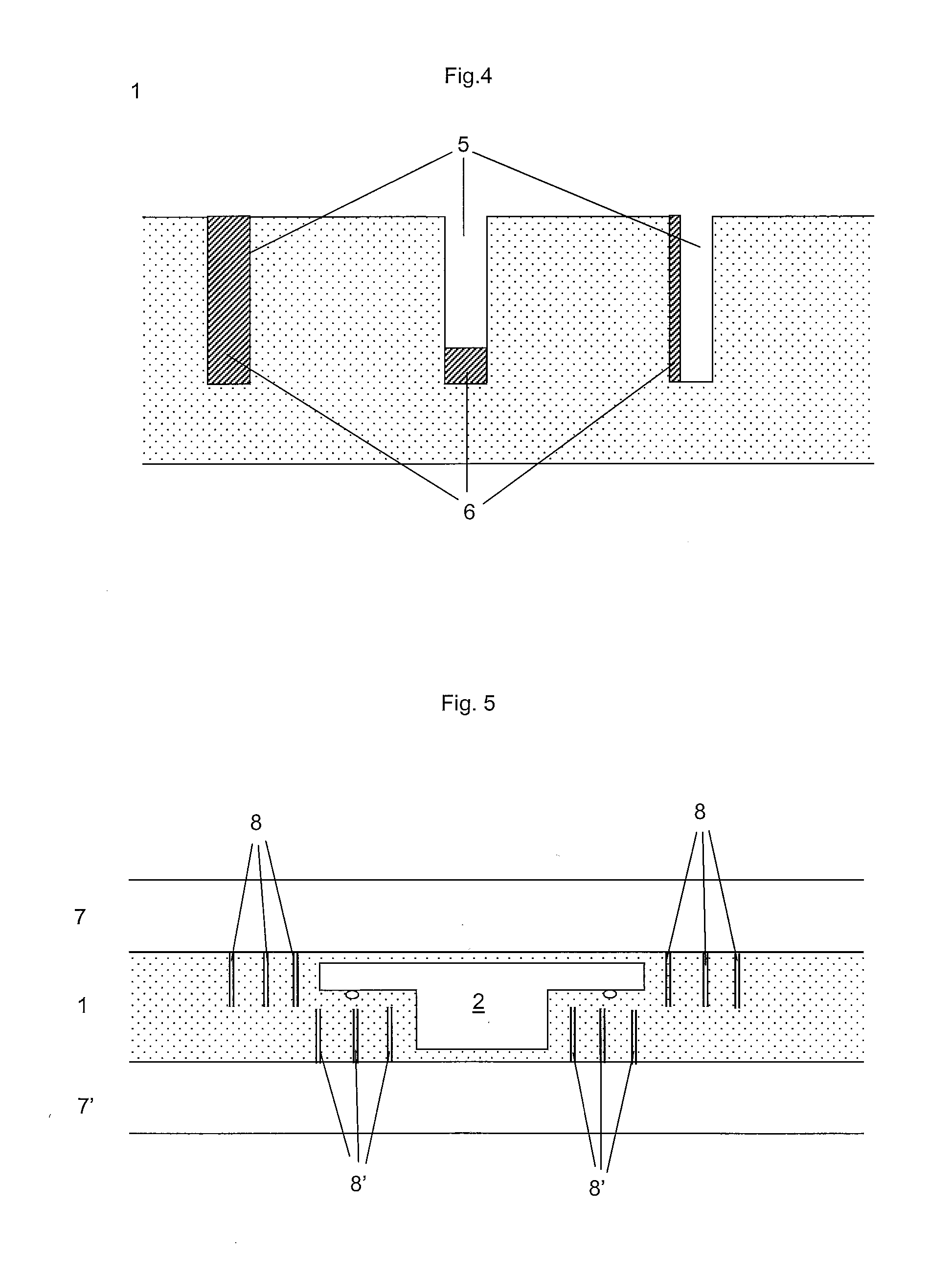
[0037]FIG. 4 is a sectional view of recesses containing an additional material,

[0038]FIG. 5 is a sectional view of a functional laminate according the invention

[0039]FIG. 1 shows a sectional view of an inlay 1 with a functional component 2, e.g. a RFID chip module with module pads 3 for connection with wires 4 forming an antenna loop. The inlay 1 formed of at least two layers which have been laminated together with a functional element 2, such that the functional element 2 is at least partially embedded ...


PUM

PropertyMeasurementUnit
Widthaaaaaaaaaa
Magnetismaaaaaaaaaa

Abstract

The invention concerns a functional laminate and a method for manufacturing said functional laminate, the method comprising the following steps:—providing a substrate sheet (1);—inserting at least one functional component (2) into the substrate sheet (1);—wearing out the substrate sheet (1) and/or at least one layer laminated to the substrate sheet (1) in an area adjacent to the functional component (2) resulting in at least one recess (5) with a small width in proportion to dimensions of the functional component (2) before at least one lamination step;—carrying out at least one lamination step, wherein the substrate sheet (1) is laminated with at least one additional layer by heat and/or pressure and/or gluing in such a manner that the width of the at least one recess (5) is considerably reduced or the at least one recess (5) is barely shut at least by surrounding material after lamination by virtue of shrinking of the substrate sheet (1) and/or the at least one additional layer.

Description

FIELD OF THE INVENTION[0001]The invention refers to a method for manufacturing a functional laminate and to a functional laminate produced by this method.BACKGROUND OF THE INVENTION[0002]Functional laminates are documents resulting from the lamination of a plurality of layers. In particular they are used as security documents such as smart cards, ID cards, credit cards and the like.[0003]The notion of functional laminates also refers to semi-finished products like prelaminates or inlays, which are used for example for the manufacturing of smart cards equipped with functional components such as chips or chip modules, RFID antennas, switches and the like. They usually comprise a number of layers, in which the chip module is embedded in at least one of the layers. The layers are usually made of a plastic material such as polycarbonate or polyethylene terephthalate.[0004]When the layers are laminated using heat and / or pressure, the macromolecules of the plastic material tend to shorten ...

Claims


Application Information

Patent Timeline
IPC IPC(8): B42D15/00B32B7/04B32B38/04B32B27/00B32B37/02B32B37/14
CPCB32B37/144B42D25/378B32B2305/347B32B2307/736B32B2425/00B32B2519/02B42D2033/20B42D2033/46B42D2035/30G06K19/077G06K19/07728B42D25/00B42D25/455B42D25/333Y10T428/2462Y10T428/24612B42D25/45B32B38/04
Inventor MICHALK, MANFRED
Owner HID GLOBAL GMBH
Why Eureka
Try Eureka