Plant for treatment of liquid as well as method for controlling such a plant

a plant and liquid treatment technology, applied in the direction of sustainable biological treatment, water/sewage treatment by oxidation, biological water/sewage treatment, etc., can solve the problems of reducing the efficiency of liquid treatment, and reducing the cost of operation, so as to achieve constant liquid flow speed and reduce the effect of operation costs

Active Publication Date: 2017-05-25
XYLEM EURO GMBH
View PDF2 Cites 0 Cited by
  • Summary
  • Abstract
  • Description
  • Claims
  • Application Information

AI Technical Summary

Benefits of technology

[0008]The present invention aims at improving previously known methods for controlling treatment plants with the object of reducing the costs for the operation of the treatment plant and thereby providing an improved method for controlling a treatment plant suitable for treatment of liquid. A basic object of the invention is to provide an improved method of initially defined type, which entail that a constant speed of the liquid flow can be achieved without the need for external speed sensors. External speed sensors suffer from the drawbacks that they are expensive and require monitoring and maintenance as they are susceptible to disturbances and thereby risk to provide incorrect information.

Problems solved by technology

Purified waste water is released into the nature and in the case the water bound nitrogen is not eliminated there is a risk for eutrophication in the natural watercourses, and due to the fact that the biological material is consuming considerable amounts of oxygen watercourses deficient in oxygen are generated if insufficiently purified water is released.
The changing speed of the liquid flow may be compensated by revising the operational speed of the flow generating machine, however, this demands for the speed of the liquid flow being monitored by means of expensive speed sensors that are susceptible to disturbances and require regular maintenance.

Method used


Image

  • Plant for treatment of liquid as well as method for controlling such a plant
  • Plant for treatment of liquid as well as method for controlling such a plant
  • Plant for treatment of liquid as well as method for controlling such a plant

Examples


Embodiment Construction

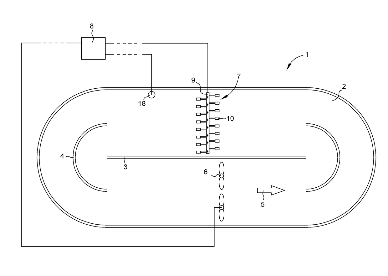
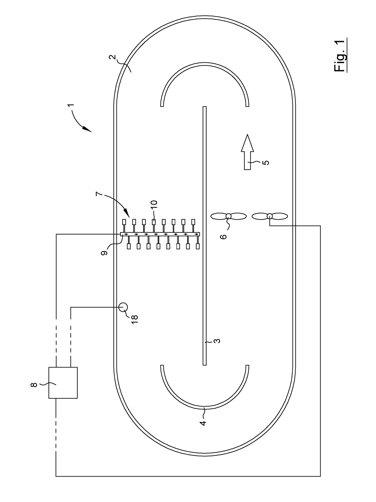
[0022]Reference is initially made to FIG. 1. The present invention relates to a plant, generally designated 1, suitable for treatment / purification of liquid, such as waste water, comprising biological matter. The plant 1 comprises a basin 2, configured to house the liquid to be treated.

[0023]In the disclosed embodiments the plant is constituted by a treatment plant and the description hereinbelow is written using the term treatment plant, but it shall be realized that other equivalent plants are included if nothing else is stated. Thereto the basin 2 is constituted by a circulation channel in the disclosed embodiments and the description hereinbelow is written using the term circulation channel, but it shall be realized that also basins that are not circulation channels are to be seen as equivalents and be included if nothing else is stated.

[0024]Thus, the treatment plant 1 comprises an endless circulation channel 2, or race track, configured to house the liquid to be treated. In th...


PUM

PropertyMeasurementUnit
filling heightaaaaaaaaaa
momentumaaaaaaaaaa
torqueaaaaaaaaaa

Abstract

A plant and method for controlling such a plant suitable for treatment of waste water. The plant includes a basin, a flow generating machine adapted to generate a liquid flow in the basin, equipment in the basin that effects the momentum of the liquid flow, and a control unit. The method includes the steps of: storing a predetermined relationship between the operational speed N of the flow generating machine and an operational parameter P from which the torque M of the flow generating machine may be derived, determining the operational speed N, determining a set value of the operational parameter P of the flow generating machine, determining a real value of the operational parameter P of the flow generating machine, and adjusting the operational speed N if the real value of the operational parameter P is different than the set value of the operational parameter P.

Description

TECHNICAL FIELD OF THE INVENTION[0001]The present invention relates in general to a plant and a method for controlling a plant for treatment of liquid, especially biological treatment of liquid. The present invention relates especially to a plant and a method for controlling a plant suitable for treatment of liquid such as waste water, wherein the plant comprises a basin configured to house a liquid, at least one flow generating machine arranged in the basin and configured to generate a liquid flow in the basin, at least one equipment that is arranged in the basin and that effects the momentum of the liquid flow, and a control unit that is operatively connected to said at least one flow generating machine.BACKGROUND OF THE INVENTION AND PRIOR ART[0002]A circulation channel, or a ring channel, is usually an upwardly open endless basin that is used during biological treatment or oxidation of liquid, especially waste water. The waste water / liquid is made to flow along the circulation c...

Claims


Application Information

Patent Timeline
Patent Type & Authority Applications(United States)
IPC IPC(8): C02F3/00B01F5/10B01F3/04C02F3/12B01F27/71
CPCC02F3/006C02F3/1257C02F3/1284B01F5/104B01F2215/0052B01F3/04773C02F2209/006C02F2209/40B01F3/04765C02F3/00C02F3/14C02F3/16C02F7/00C02F2201/002C02F2209/22B01F23/2342B01F23/23421B01F25/51Y02W10/10C02F3/02C02F1/74B01F23/20B01F25/50B01F25/52B01F2101/305
Inventor UBY, LARS
Owner XYLEM EURO GMBH
Why Eureka
Try Eureka