
Front wheel suspension for a single-track vehicle

Active Publication Date: 2012-07-19
TREBICHAVSKY MARTIN
View PDF3 Cites 1 Cited by
  • Summary
  • Abstract
  • Description
  • Claims
  • Application Information

AI Technical Summary

Benefits of technology

[0010]The present invention aims to provide a front wheel suspension for a single-track vehicle of the initially defined kind, which minimizes or eliminates the above-mentioned disadvantages and problems of known embodiments and, in particular, provides an improved spring suspension at an improved steerability and, in particular, a reduced movable and unsprung mass as well as an improved introduction and distribution of forces.
[0011]To solve these objects, a front wheel suspension for a single-track vehicle of the initially defined kind is essentially characterized in that the steering bar is comprised of a fork bar partially encompassing the front wheel, which fork bar, on its ends facing away from the handlebar, is coupled to the fork-like wheel carrier via the lever connection. Due to the fact that a lever connection for coupling the steering bar to the fork-like wheel carrier and an articulated connection of the wheel carrier to at least one frame bar, which connection is separated from the wheel carrier, are provided for the front wheel suspension, it has become possible to provide, in particular, a structurally simple embodiment that complies with the above-mentioned requirements, above all as regards an improved spring suspension at a minimum response delay time, a direct steering, and the provision of a low unsprung mass. In addition, it has become possible by the construction according to the invention to minimize, or distribute to different points on the frame, the loads acting on the frame and to be transmitted, so as to also reduce the demands placed on the frame or chassis of the single-track vehicle. In order to provide a sufficiently large steering lock at a simultaneously low mass moment of inertia about the steering axle, it is proposed that the articulated connection has a substantially vertical pivot axis substantially in a line between the articulated mounting of the steering bar on the frame and the support of the front wheel on the wheel carrier and substantially parallel to the steering bar. To further improve the introduction and distribution of the forces to be introduced into the frame, it is proposed according to the invention that the steering bar is comprised of a fork bar partially encompassing the front wheel, which fork bar, on its ends facing away from the handlebar, is coupled to the fork-like wheel carrier via the lever connection.

Problems solved by technology

The spring element acts directly on a lower longitudinal handlebar and is supported on the frame, wherein it is immediately apparent that the multitude of handlebars and joints to be used calls for an extremely complex construction.
The disadvantages, as already pointed out above, generally include extremely complex structures and the associated high weights as well as a substantially indirect steering.
Due to the fact that no steerability of a rear wheel is provided, such suspensions for the rear wheels of a two-wheel vehicle, in particular a bicycle, cannot be directly compared to, or combined with, the above-identified configurations of front wheel suspensions.
In addition, all of the above-mentioned embodiments involve the disadvantage that, due to their constructions, they have limited ranges of spring, which are particularly insufficient in single-track off-road vehicles such as motocross bikes or all-terrain bikes or mountain bikes or the like.

Method used


Image

  • Front wheel suspension for a single-track vehicle
  • Front wheel suspension for a single-track vehicle

Examples


Embodiment Construction

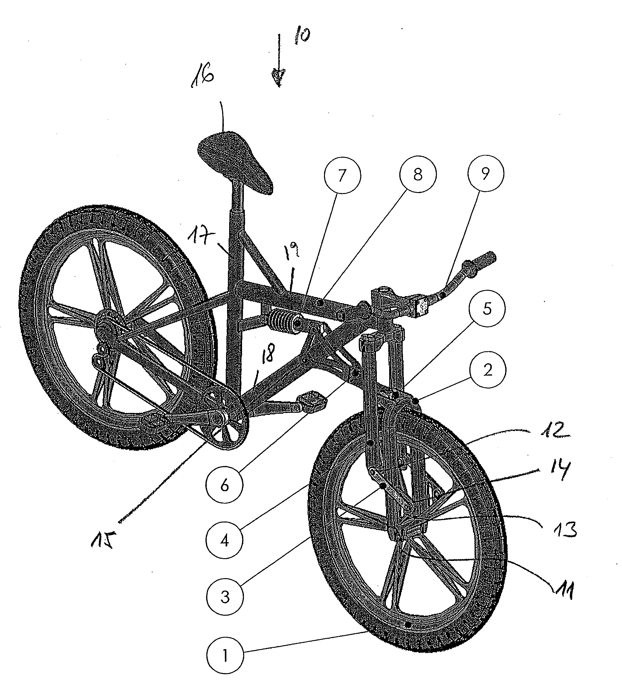
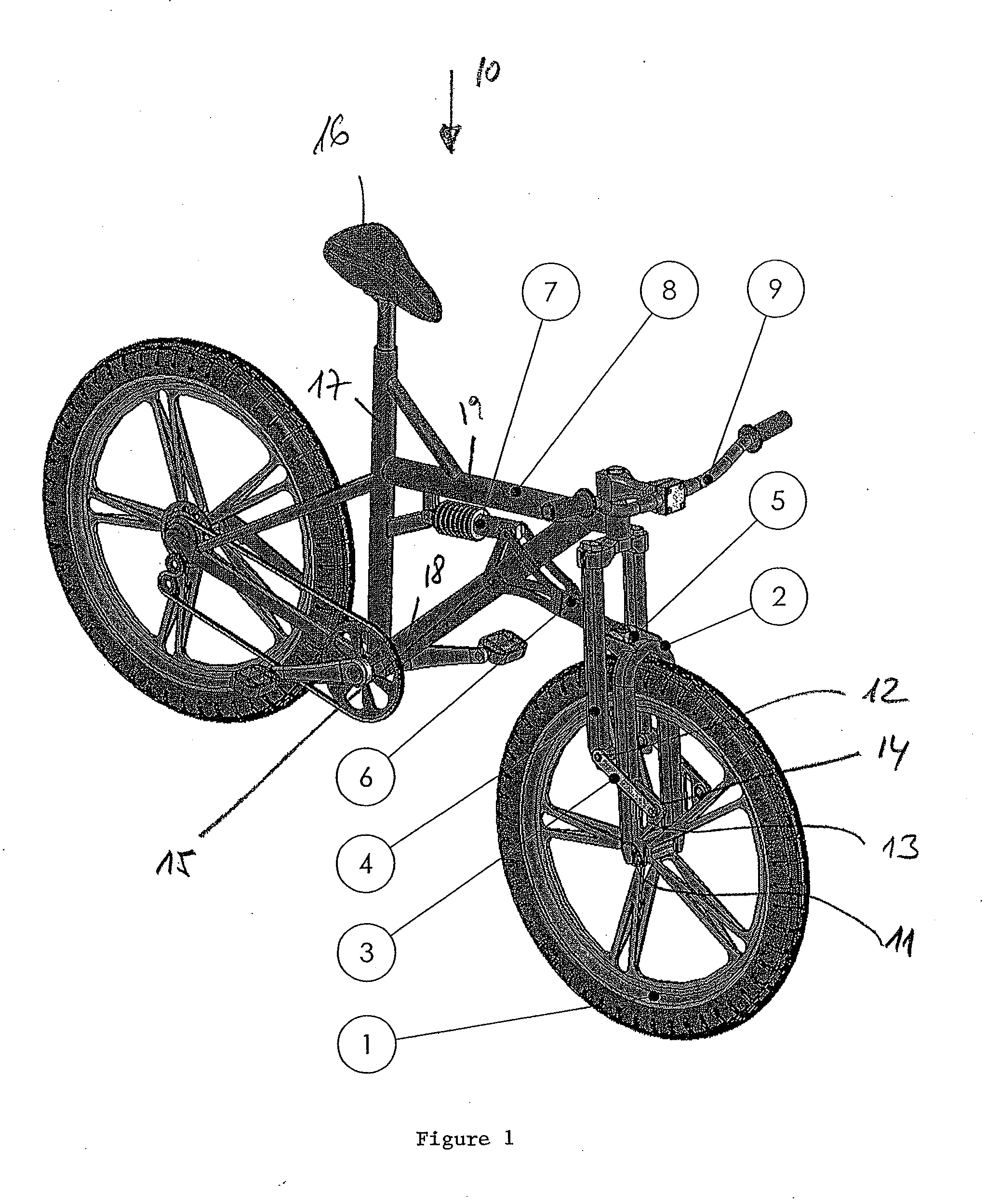
[0030]From the bike illustrated in the FIGURE, which is generally denoted by 10, it is apparent that a front wheel 1 is mounted on a fork-shaped wheel carrier 2, an axis of the mounting of the front wheel 1 on the ends of the fork-like wheel carrier 2 being denoted by 11.

[0031]On the one hand, the fork-shaped wheel carrier 2 on its two bars is each connected via a lever connection or lower swing arm 3 to a steering fork bar 4 at least partially encompassing the front wheel 1, wherein the steering bar 4 is coupled to a handlebar denoted by 9 in a manner known per se. In addition to the articulated coupling of the lever connection 3 in the region of the axis 12 on the lower ends of the steering bar 4, a further articulated connection on an element 13 coupled to the fork-like wheel carrier 2 is denoted by 14.

[0032]In addition, the fork-like wheel carrier 2, on its end facing away from the axle 11 mounting the front wheel 1, is coupled to the frame generally denoted by 8 via a joint 5 p...


PUM


Abstract

The invention relates to a front wheel suspension for a single-track vehicle, wherein a front wheel is rotatably supported on a fork-like wheel carrier and the wheel carrier is coupled to a frame and a steering bar of the vehicle connected to a handlebar, wherein the steering bar is coupled to the wheel carrier by means of a lever connection. Furthermore the wheel carrier is coupled to at least one frame bar by means of an articulated connection, and the articulated connection has a substantially vertical pivot axis. Moreover the steering bar is comprised of a fork bar partially encompassing the front wheel, which fork bar is coupled to the wheel carrier via the lever connection. Thereby a front wheel suspension having improved characteristics in regard to the suspension, the direct handling of the steering, and a reduction of the load of the frame can be provided.

Description

[0001]This is a national stage of PCT / AT2010 / 000356 filed Sep. 29, 2010 and published in German, which has a priority of Austria No. A 1555 / 2009 filed Oct. 2, 2009, hereby incorporated by reference.FIELD OF THE INVENTION[0002]The present invention relates to a front wheel suspension for a single-track vehicle, in particular a motorcycle, bicycle, or the like, wherein a front wheel is rotatably supported on a fork-like wheel carrier and the wheel carrier is or can be coupled to a frame and a steering bar of the vehicle connected to a handlebar, wherein the steering bar is coupled to the wheel carrier by means of a lever connection, wherein the wheel carrier is coupled to at least one frame bar by means of an articulated connection separate from the wheel carrier, and wherein the articulated connection has a substantially vertical pivot axis substantially in a line between the articulated mounting of the steering bar on the frame and the support of the front wheel on the wheel carrier...

Claims


Application Information

Patent Timeline
IPC IPC(8): B62K25/04
CPCB62K25/24
Inventor TREBICHAVSKY, MARTIN
Owner TREBICHAVSKY MARTIN
Learn More