Rotating device

a rotating device and rotating shaft technology, applied in the direction of bearings, shafts and bearings, instruments, etc., can solve the problems of reducing affecting the resistance of motors to shock and vibration, and poor capillary force, so as to improve the rigidity of bearings and reduce the leakage of lubricants

Inactive Publication Date: 2012-07-19
SAMSUNG ELECTRO MECHANICS JAPAN ADVANCED TECHNOLOGY CO LTD
View PDF11 Cites 21 Cited by
  • Summary
  • Abstract
  • Description
  • Claims
  • Application Information

AI Technical Summary

Benefits of technology

[0015]According to the present invention, the rigidity of a be...

Problems solved by technology

According to this structure, however, when the thickness of a motor is restricted, it is necessary to reduce the dimension of the dynamic pressure generator in the direction of the rotation axis R. This reduces the rigidity of a bearing and harms the resistances of the motor against shock and vibration.
Alternatively, it is necessary to reduce the dimension of the tapered seal in the direction of the rotation axis R. In this case, in orde...

Method used


Image

  • Rotating device
  • Rotating device
  • Rotating device

Examples


first embodiment

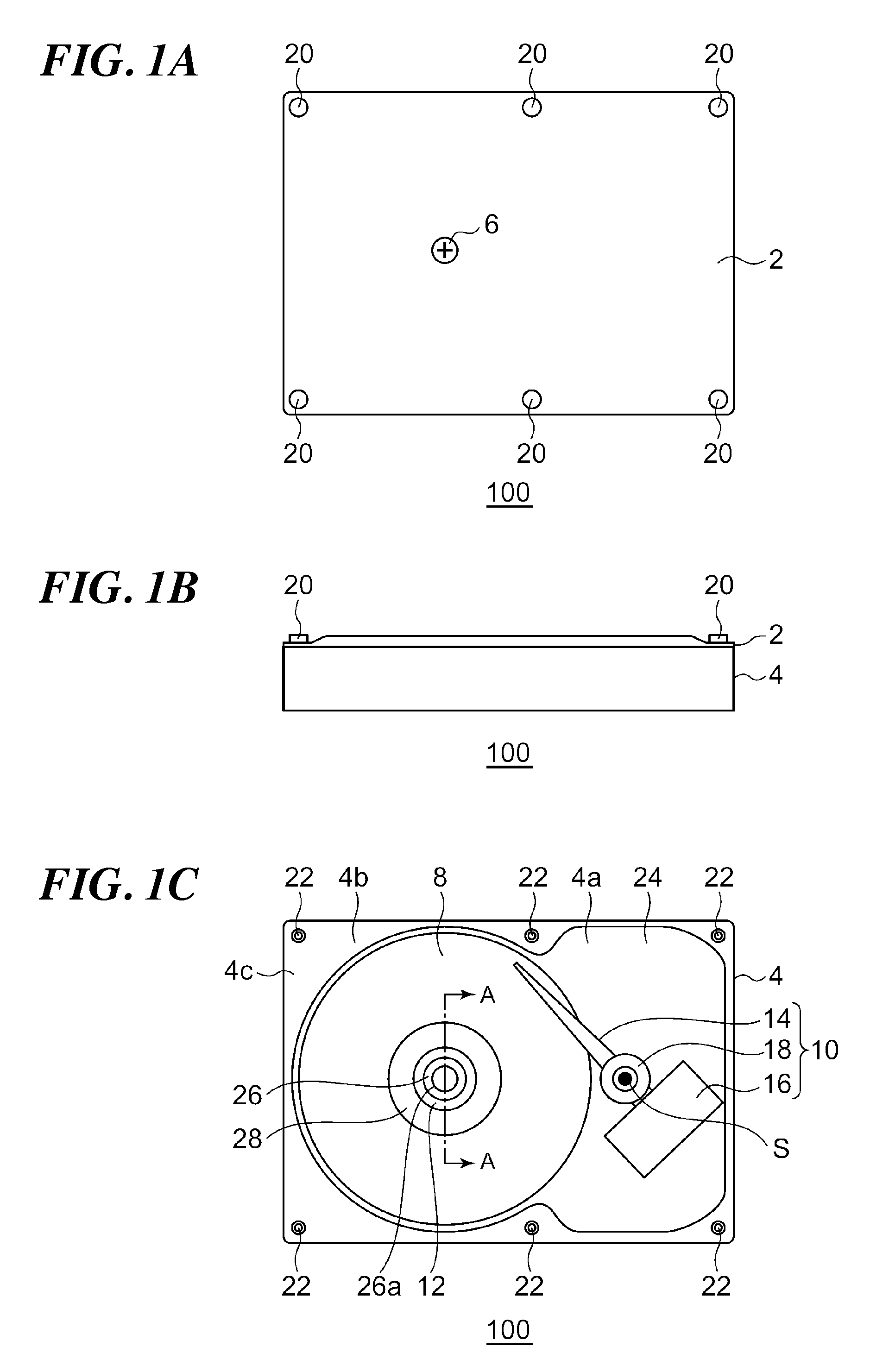
[0031]FIGS. 1A to 1C are diagrams showing a rotating device 100 according to a first embodiment. FIG. 1A is a top view of the rotating device 100. FIG. 1B is a side view of the rotating device 100. FIG. 1C is a top view of the rotating device 100 with a top cover 2 being detached. The rotating device 100 includes a fixed body, a rotating body that rotates relative to the fixed body, a magnetic recording disk 8 that is attached to the rotating body, and a data reading / writing unit 10. The fixed body includes a base 4, a shaft 26 fixed to the base 4, the top cover 2, six screws 20, and a shaft fixing screw 6. The rotating body includes a hub 28.

[0032]The explanation below will be given based on a definition that a side where the hub 28 is mounted to the base 4 is an upper side.

[0033]The magnetic recording disk 8 is a 2.5 inch magnetic recording disk formed of a glass and having a diameter of 65 mm, and has a center opening with a diameter of 20 mm and a thickness of 0.65 mm. The hub...

second embodiment

[0099]Depending on the specification of a product using the rotating device, it is desirable to reduce the cost of the whole product while accomplishing the above-explained object. Filling of a lubricant is a requisite process in manufacturing of the rotating device, but if such a requisite process can be simplified, the cost of the rotating device can be reduced, thereby reducing the cost of the whole product. An explanation below will be given in detail of a rotating device of a second embodiment which employs a configuration appropriate for such an application with reference to the accompanying drawings.

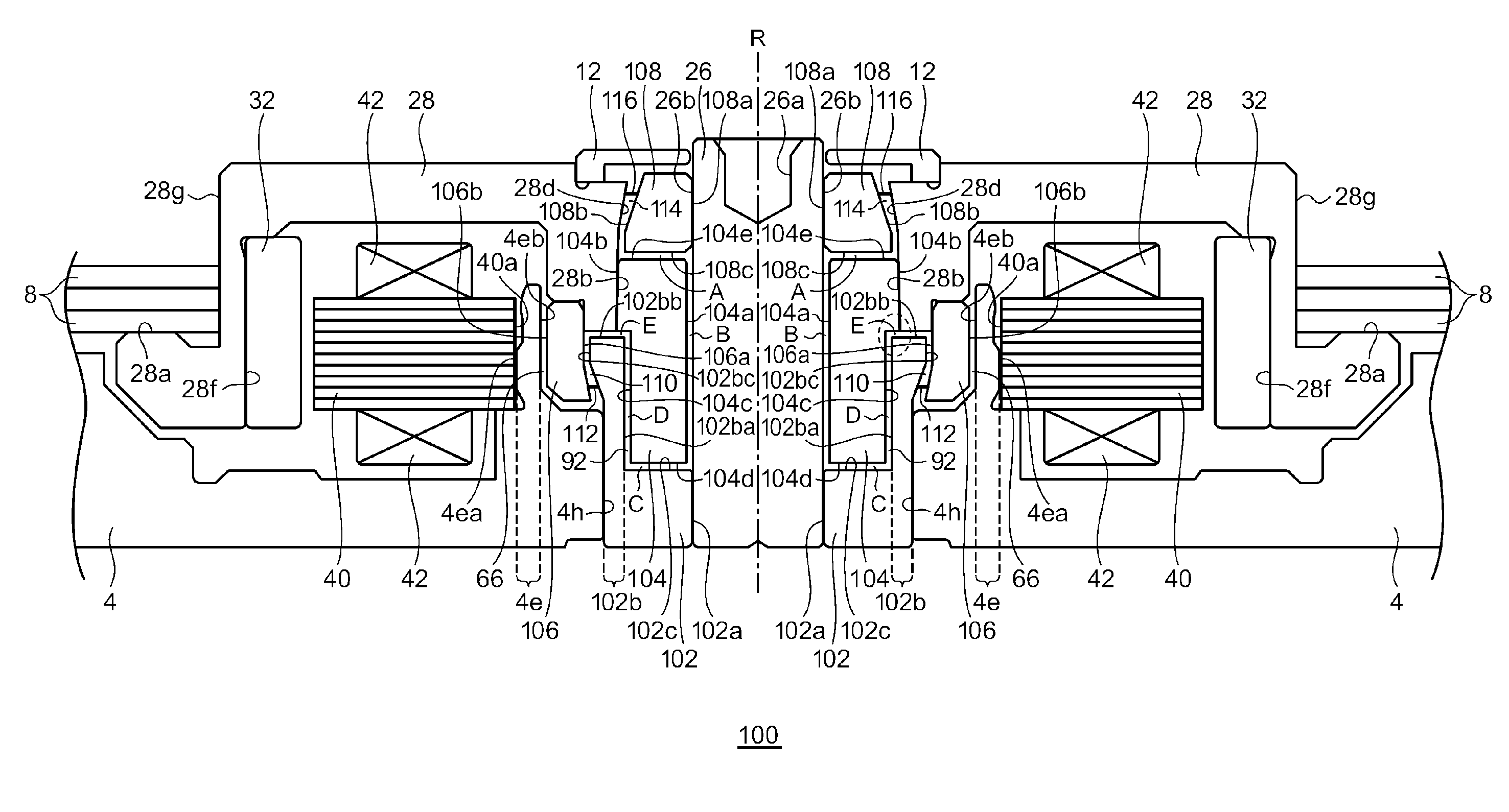
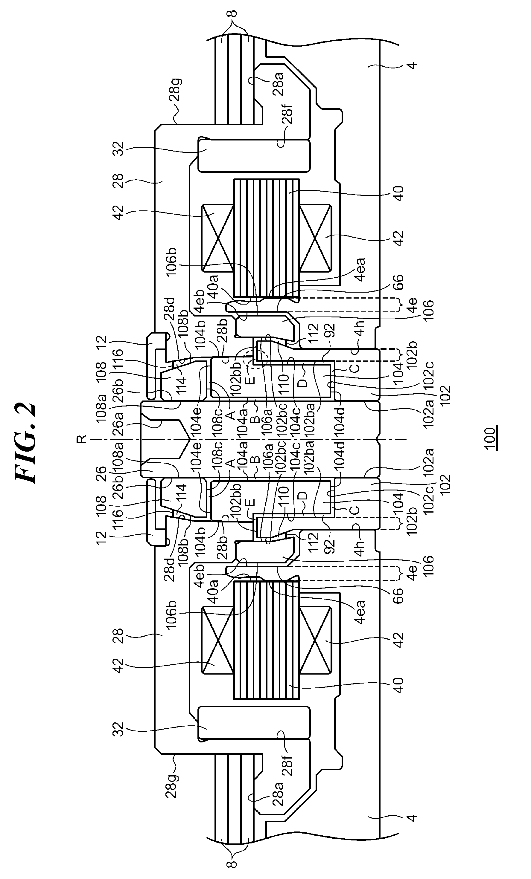
[0100]Like the first embodiment, a rotating device of the second embodiment is also a shaft-fixed type disk drive device. The same structural element as that of the first embodiment will be denoted by the same reference numeral, and the detailed explanation thereof will be omitted for clarity. The explanation below will be mainly given of the different part from the first embodime...


PUM


Abstract

A rotating device includes a fixed body having a base and a shaft, a hub, and a rotating body having a rotating-body-side encircling member fixed to the hub and encircling the shaft. A lubricant is present between the fixed body and the rotating body. The rotating-body-side encircling member and the shaft are each formed with a radial dynamic pressure generating groove. The fixed body includes a base-side encircling member having a disk part encircling the base-side portion of the shaft and a cylinder part encircling the rotating-body-side encircling member. The base-side encircling member has the disk part fixed to the shaft by interference fitting, and has the cylinder part fixed to the base. An air-liquid interface is located in a gap in the radial direction between the inner periphery of the cylinder part and the outer periphery of the rotating-body-side encircling member.

Description

CROSS-REFERENCE TO RELATED APPLICATION[0001]The present application claims the priorities based on Japanese Patent Application No. 2011-006827 filed on Jan. 17, 2011, Japanese Patent Application No. 2011-121322 filed on May 31, 2011 and Japanese Patent Application No. 2011-121981 filed on May 31, 2011, the entire disclosures of which are herein incorporated by reference in this specification.BACKGROUND OF THE INVENTION[0002]1. Field of the Invention[0003]The present invention relates to a rotating device that has a shaft fixed to a fixed body.[0004]2. Description of the Related Art[0005]Disk drive devices like a hard disk drive are well developed for reduction in size and increase of a volume, and are built in various electronic devices. In particular, such disk drive devices are nowadays built in portable electronic devices, such as a laptop computer and a portable music player. In comparison with disk drive devices built in a so-called stationary electronic device like a desktop P...

Claims


Application Information

Patent Timeline
IPC IPC(8): F16C32/06
CPCG11B19/2036F16C2370/12F16C32/0603F16C17/107F16C33/745
Inventor SUGIKI, RYUSUKE
Owner SAMSUNG ELECTRO MECHANICS JAPAN ADVANCED TECHNOLOGY CO LTD
Why Eureka
Try Eureka