
Dryer for bomb disposal suits

a technology for bomb disposal suits and drying racks, which is applied in the field of drying racks for bomb disposal suits, can solve the problems of not being able to adequately distribute the drying air of bomb disposal suits, being bulky and heavy, and being difficult to carry around

Inactive Publication Date: 2012-07-26
WILLIAMS BOOT & GLOVE DRYERS
View PDF18 Cites 17 Cited by
  • Summary
  • Abstract
  • Description
  • Claims
  • Application Information

AI Technical Summary

Benefits of technology

[0005]The bomb disposal suit dryer described in the present disclosure employs a heater / dryer / air distribution manifold subassembly to which is readily attached separate pairs of vertical riser members extending upwardly therefrom in cantilever or free standing onto which the individual garments or portions of the bomb disposal suit may be dressed. The system of the present disclosure employs one type of free standing vertical rack pair suited for the pants of the bomb disposal suit with interconnecting cross piece and arcuate diffuser and a second adjacent vertical rack pair with arms and spherical top suitable for hanging and drying the jacket and helmet. The combination heater / dryer / manifold is supported by a support structure, disclosed in one version as a pair of beams which are readily attached thereto by the user and which beams are in turn supported on rollers or castors for ease of transport. If desired, an additional low riser rack having a pair of vertical supports and interconnecting piece with diffuser may be attached to the manifold for providing forced air drying of the “diaper.” The drying system of the present disclosure is thus uniquely configured for the bulk and weight of forced air drying bomb disposal suits and yet may be packaged and shipped to the user in a disassembled state and readily and easily assembled on site by the user with minimal tools.

Problems solved by technology

Protective garments worn by personnel charged with disposal of bombs and explosive devices are by their very nature heat insulating, bulky and heavy.
In view of the weight and bulk of such suits, which with helmet weight about 70 pounds, ordinary drying racks designed for first responder protective garments such as, for example, those worn by firefighters, are not designed for the weight of a bomb disposal suit or adequately configured for adequate drying air distribution of such a suit.

Method used


Image

  • Dryer for bomb disposal suits
  • Dryer for bomb disposal suits
  • Dryer for bomb disposal suits

Examples


Embodiment Construction

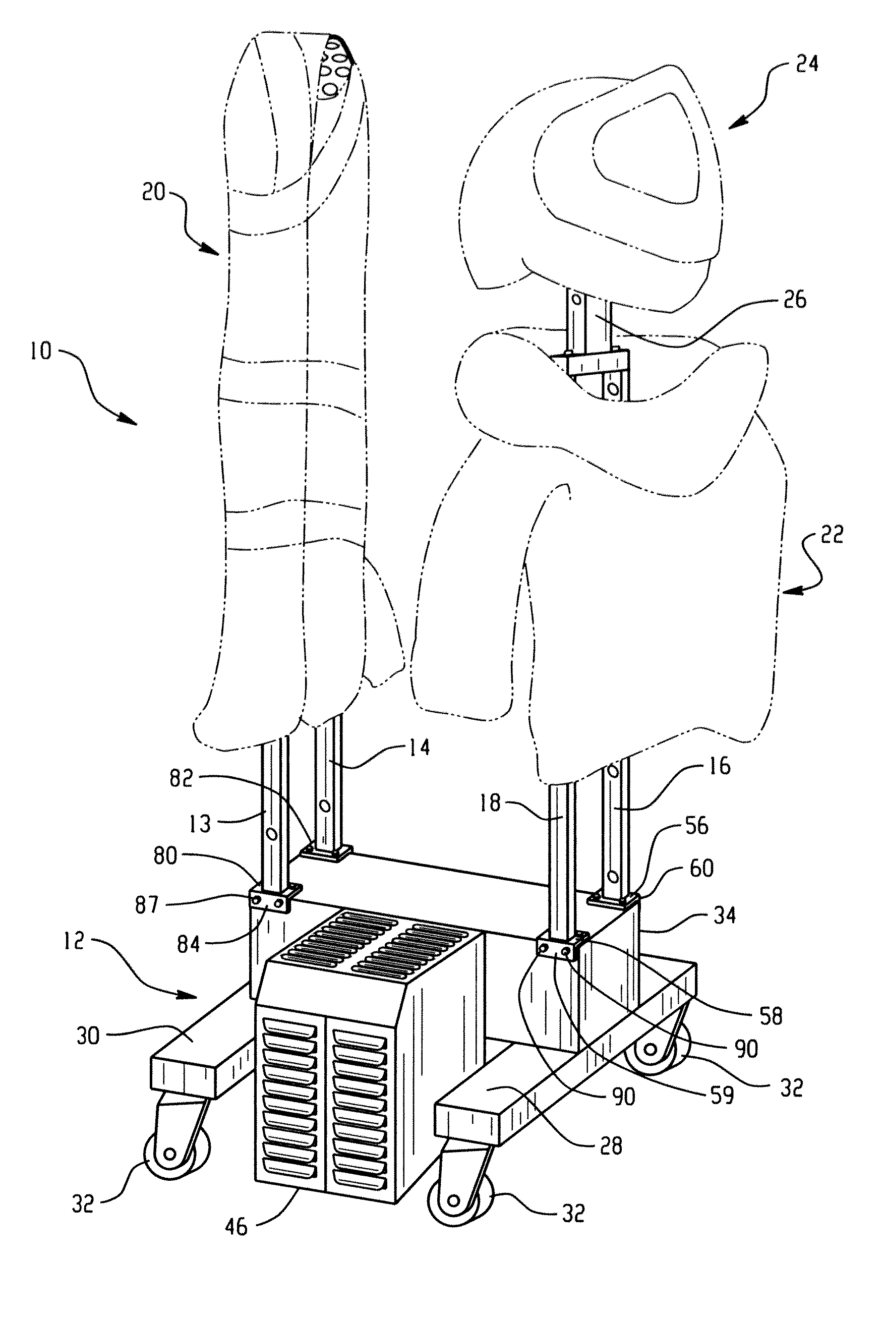
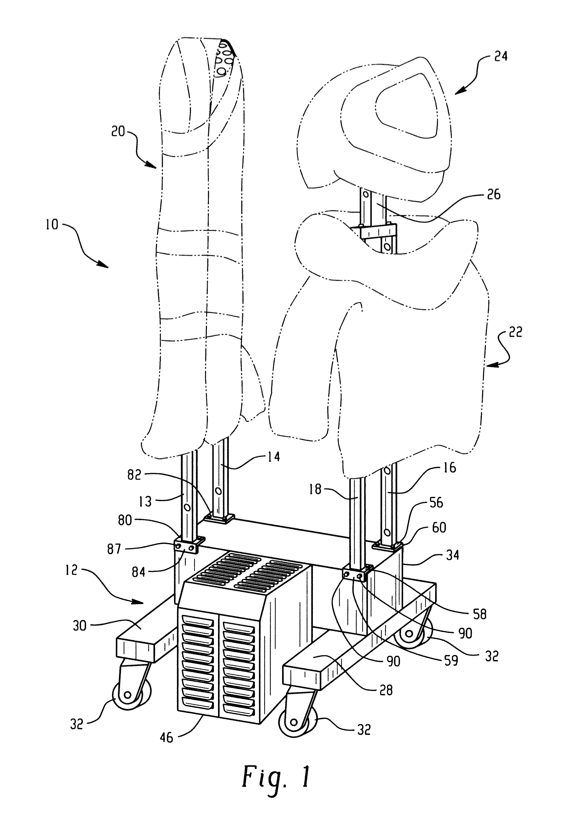
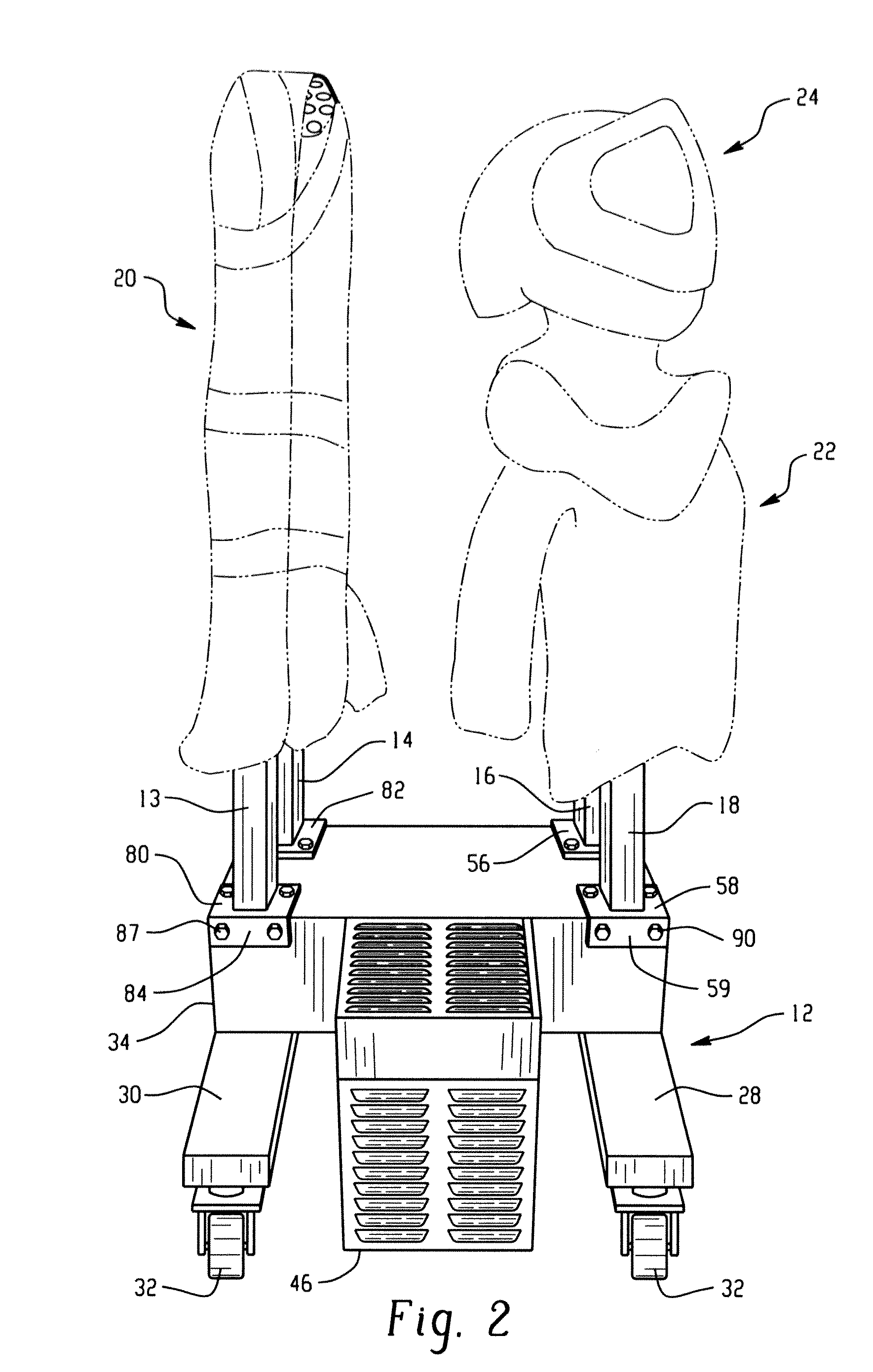
[0027]Referring to FIGS. 1 and 2, the dryer system of the present disclosure is indicated generally at 10 and includes a combination heater / dryer / manifold subassembly indicated generally at 12 with free standing uprights or vertical tubes 13, 14, 16, 18 dressed with and supporting the garments of a bomb disposal suit. The suit is shown in dashed line as comprising pants indicated generally at 20 disposed over tubes 13, 14, a jacket indicated generally at 22 disposed over tubes 16, 18 and a helmet indicated generally at 24 supported on a member 26 attached to uprights 16, 18. Subassembly 12 is supported by support beams 28, 30 which are each provided with a pair of rollers or casters denoted by reference numeral 32.

[0028]Referring to FIGS. 3 and 4, the system 10 of FIG. 1 is shown with the suit garments removed and shows the heater / blower / manifold subassembly 12 as comprising an air distribution manifold 34 shown separately in FIG. 4 having a plurality of air outlets 36, 38 formed in...


PUM


Abstract

A readily assembled and disassembled portable forced air dryer system for bomb disposal suits having a subassembly of a blower / heater housing and air discharge manifold and releasably attached support members with removable rollers, which may be castered. A first riser rack with tubes ported for air discharge and a baseplate is releasably assembled to the manifold for effecting forced air drying of pants for the suit received on the rack. A second riser rack with tubes ported for air discharge and a baseplate is releasably assembled to the manifold for effecting forced air drying of a jacket and helmet of the suit. The subassembly, first and second rack, support members may be disassembled, packaged and transported with assembly fasteners as a kit.

Description

[0001]This application claims the benefit of priority to U.S. Provisional Application No. 61 / 431,969, filed Jan. 12, 2011, entitled “Dryer for Bomb Disposal Suits,” by Gary Williams, which is hereby incorporated by reference in its entirety.BACKGROUND [0002]Protective garments worn by personnel charged with disposal of bombs and explosive devices are by their very nature heat insulating, bulky and heavy. Typically, such garments or suits comprise pants, a jacket, groin armor or “diaper” and helmet with face mask. In view of the nature of the usage and construction of such suits, it is necessary that after each usage they are forced air dried to prevent growth of fungus and mold and for preservation and sanitation purposes. In view of the weight and bulk of such suits, which with helmet weight about 70 pounds, ordinary drying racks designed for first responder protective garments such as, for example, those worn by firefighters, are not designed for the weight of a bomb disposal suit...

Claims


Application Information

Patent Timeline
Patent Type & Authority Applications(United States)
IPC IPC(8): F26B25/20
CPCD06F59/02
Inventor WILLIAMS, GARY
Owner WILLIAMS BOOT & GLOVE DRYERS
Learn More