Homogenizing fuel enhancement system

a fuel enhancement and homogenizing technology, applied in the field of fuel systems, can solve the problems of small improvement in actual efficiency and/or were achieved, add tremendous cost and complexity to the engine, and achieve marginal success at bes

Inactive Publication Date: 2012-07-26
EXEN HLDG
View PDF2 Cites 52 Cited by
  • Summary
  • Abstract
  • Description
  • Claims
  • Application Information

AI Technical Summary

Benefits of technology

[0042]Aspects of the present invention teach certain benefits in construction and use which give rise to the exemplary advantages described below.

Problems solved by technology

As to the prior art, in sum, all known efforts to increase the efficiency of internal combustion engines have to date led to only marginal success at best.
Most such “improvements” have resulted in only a slight increase in actual efficiency and / or were achieved using approaches that are technologically or practically not workable, as either involving fuels that are not readily available or safely used or systems and hardware that add tremendous cost and complexity to the engine.
However, due to the sensitive nature of this approach to combustion and its requirement of precise temperature and pressure conditions (compression ratios) in the combustion chambers for the automatic combustion reaction to be set off, under actual road testing where an engine is subjected to various loading demands, the HCCI process breaks down, leading not only to little to no efficiency gains but in some cases to engine failures (predetonation).
Other attempts to improve the efficiency and / or reduce emissions of internal combustion engines have included fuel fractioning, additives in the air intake, which thus don't interact with the fuel until they meet in the combustion chamber, and actual fuel additives or formulations introduced into the combustion chamber in some fashion that for a variety of reasons are relatively less effective given the particular system or implementation method.
Holder states in the '664 patent that “[a]s far as the inventive concept is concerned it is unimportant whether the fuel fractions are present in gaseous or liquid form,” yet it is also stated that “the fuel mixture [is injected] into the individual combustion chambers of the internal combustion engine in the conventional manner,” such that Holder effectively does not teach or enable injection of a liquid-gaseous fuel mixture.
Other approaches in the art of bringing together multiple fuels as a common stream even ahead of injection yet involve further disadvantageous features and still without providing a desirable means to substantially homogeneously mix particularly liquid and gaseous fuels and maintain such homogeneity prior to injection.
To do so introduces a number of complexities and attendant costs to the Watanabe system.
Moreover, maintaining and dealing with these finely balanced physical fuel properties presents further challenges within the injection system, and the common rail 4, specifically.
Therefore, it is difficult to feed the additional fluid sufficiently.” Thus, Watanabe clearly teaches that the fuel constituents must be kept in a liquid or supercritical state essentially throughout the system while in operation using temperature and pressure in order to adequately mix and later inject the liquid fuel mixture.
This may also reduce fuel costs if the alternative fuels are cheaper than diesel, though not necessarily reducing overall fuel consumption or actually improving fuel efficiency.

Method used


Image

  • Homogenizing fuel enhancement system
  • Homogenizing fuel enhancement system
  • Homogenizing fuel enhancement system

Examples


Embodiment Construction

[0068]The above described drawing figures illustrate aspects of the invention in at least one of its exemplary embodiments, which aspects are further defined in detail in the following description.

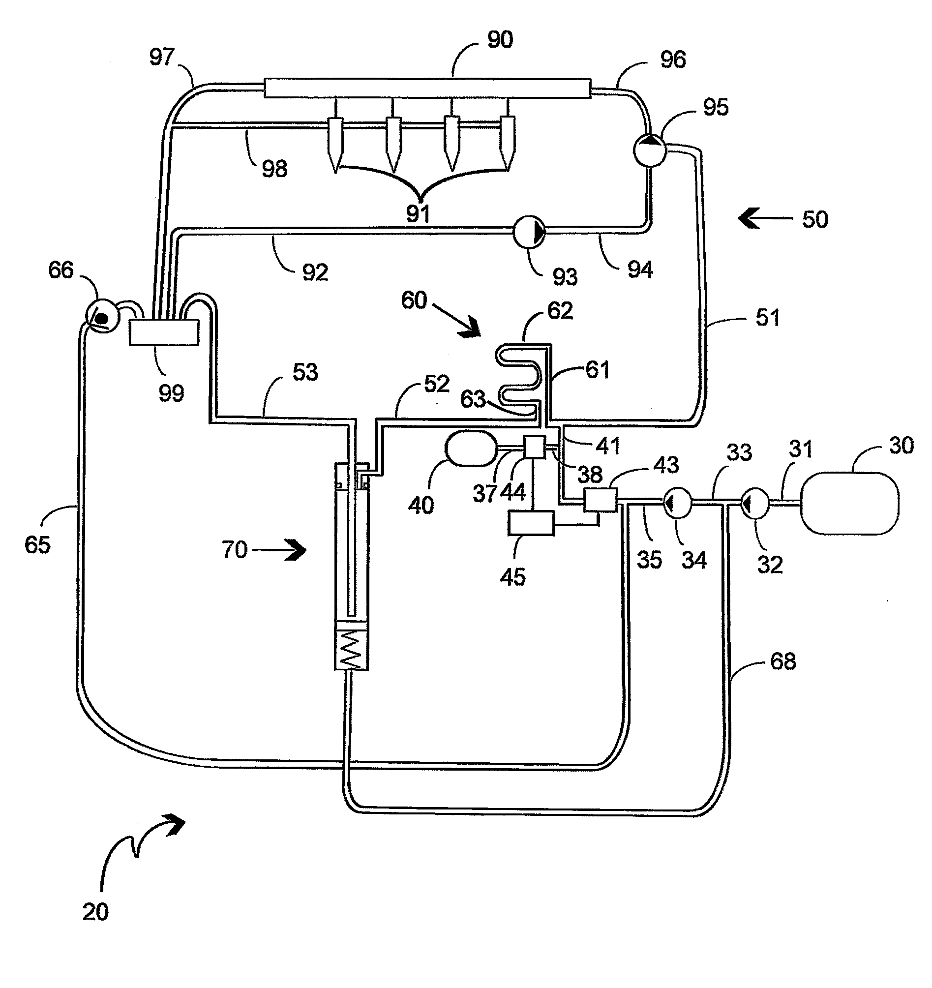
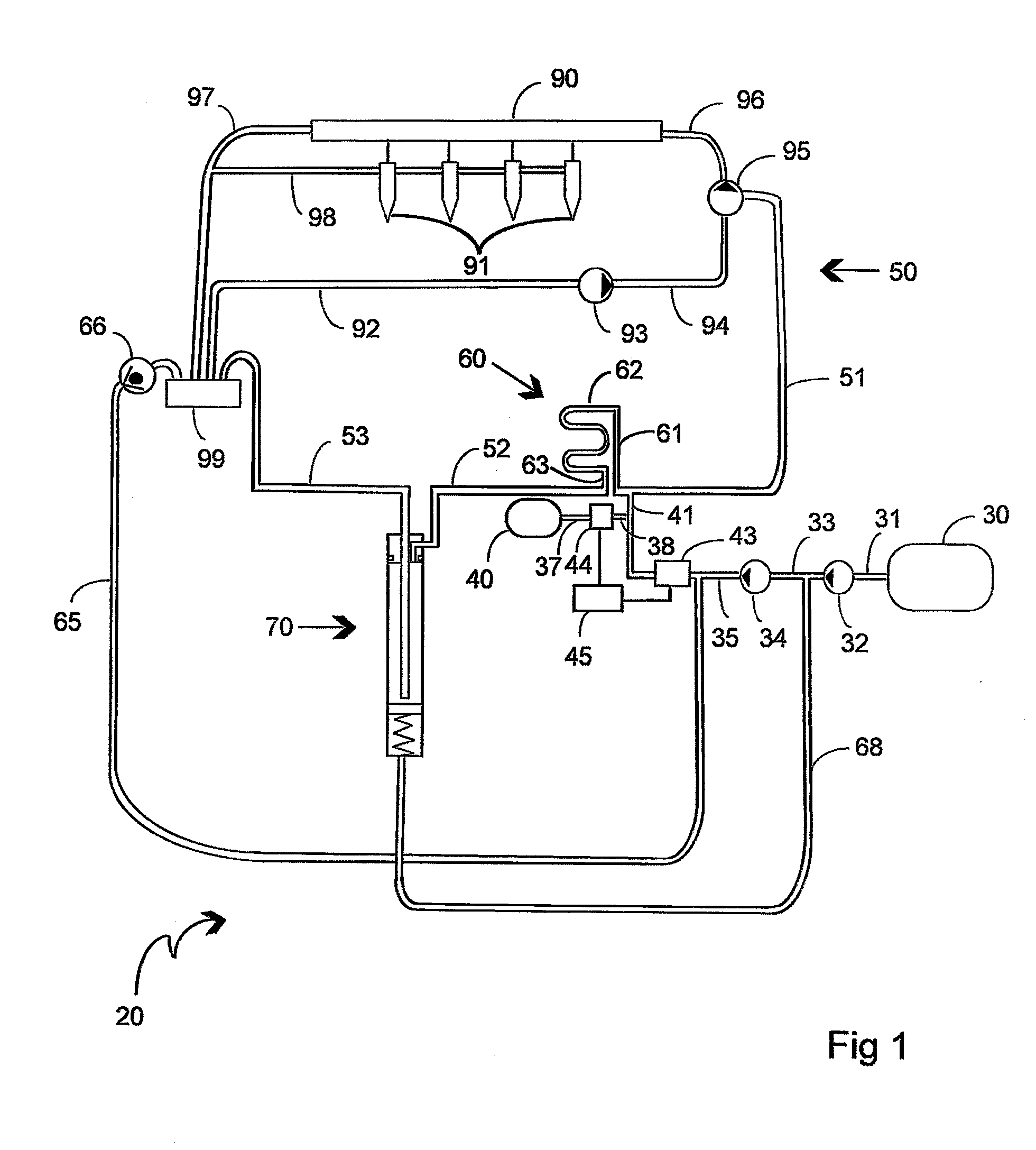
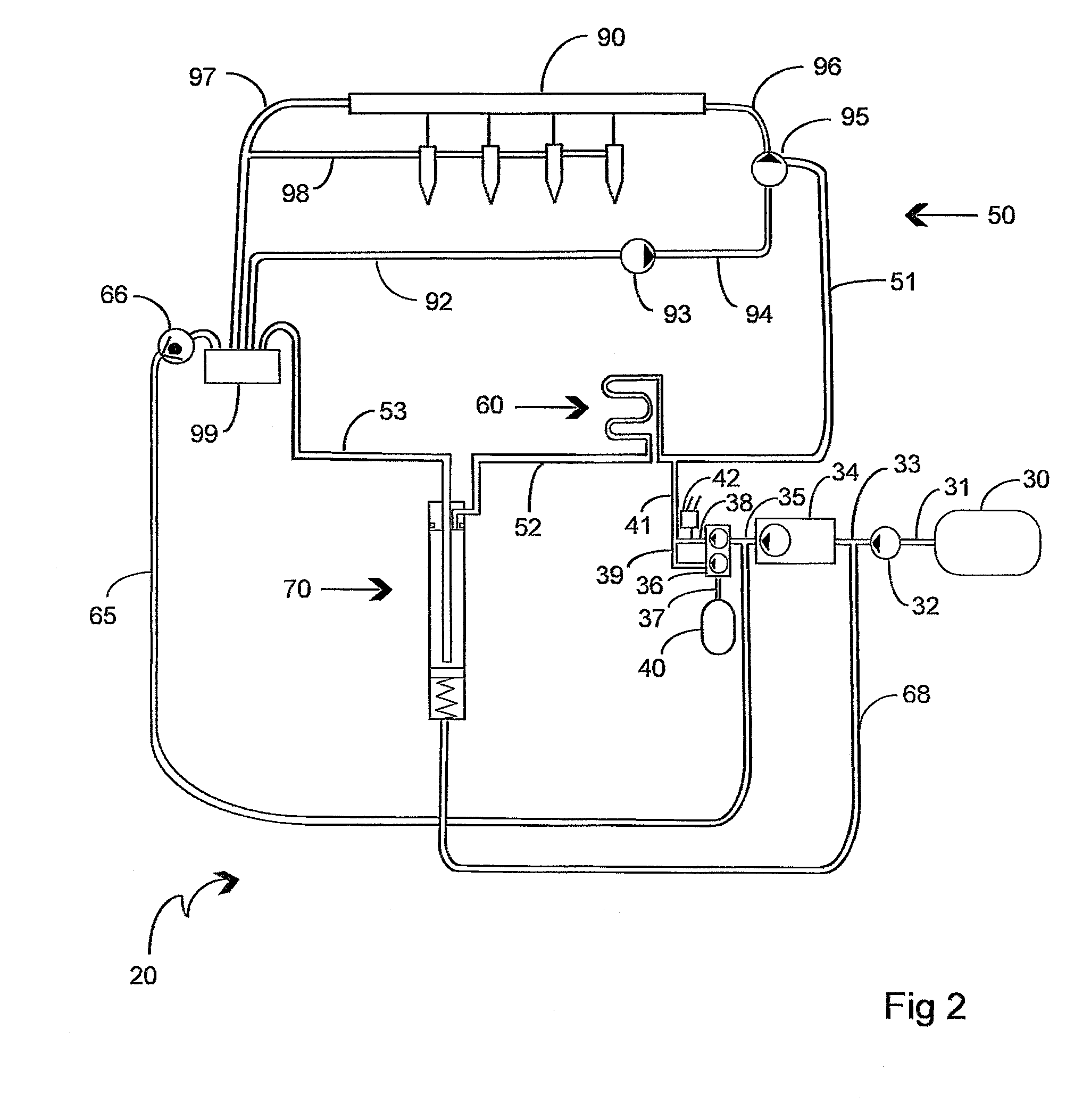
[0069]The subject of this patent application is generally an improved fuel enhancement system in various embodiments for use in connection with internal combustion engines or the like that builds on the disclosures of the above-referenced applications. Thus, while the further exemplary embodiments shown and described herein are focused on specific aspects of particularly the fuel enhancement system components relating to the mixing, circulation, and delivery of the multi-fuel mixture, here specifically in the context of common rail or mechanical injection diesel engines, it will be appreciated by those skilled in the art that the present invention is applicable to and may work in conjunction with a variety of engines, engine fuel systems, and fuels now known or later developed or discovere...


PUM


Abstract

A homogenizing fuel enhancement system involves at least one circulation loop existing outside of the injection system for continuously circulating and maintaining the homogeneity of a multi-fuel mixture apart from any demands by or delivery to the engine's injection system (whether mechanical injection or a common rail), and at least one infusion tube configured within the at least one circulation loop for providing a volumetric expansion wherein the fuel mixture is infused and thereby rendered more homogeneous.

Description

RELATED APPLICATIONS[0001]This application is a Continuation In Part of U.S. patent application Ser. No. 12 / 702,252 filed on Feb. 8, 2010, which claims priority to U.S. Provisional Application No. 61 / 150,704 Filed on Feb. 6, 2009; and is a Continuation of International Application PCT / US2010 / 051167 filed on Oct. 1, 2010, which claims priority to U.S. Provisional Application No. 61 / 247,831 filed on Oct. 1, 2009, and to U.S. patent application Ser. No. 12 / 702,252 filed on Feb. 8, 2010. The entire content of each of which is hereby incorporated by reference in its entirely.INCORPORATION BY REFERENCE[0002]Applicant(s) hereby incorporate herein by reference any and all U.S. patents and U.S. patent applications cited or referred to in this application. Specifically, Applicant(s) hereby incorporate herein by reference the entire contents of International patent application Ser. No. PCT / US2006 / 045399 filed on Nov. 24, 2006, and entitled “A Multi Fuel Co Injection System for Internal Combust...

Claims


Application Information

Patent Timeline
Patent Type & Authority Applications(United States)
IPC IPC(8): F02M21/02F02M37/04
CPCF02B1/12F02D19/0642F02D19/0668F02D19/0684F02D19/087F02D19/081F02M31/20F02M53/00F02M63/0225Y02T10/36F02D41/0027Y02T10/30
Inventor LUND, MORTEN A.
Owner EXEN HLDG
Why Eureka
Try Eureka