Common rail fuel injection control device

a control device and common rail technology, applied in the direction of electric control, fuel injecting pumps, machines/engines, etc., can solve the problems of valve sticking, valve lubrication in the sliding parts of the valve is further degraded, and the trend of valve sticking is further increased, so as to improve the traceability of common rail pressure

Inactive Publication Date: 2005-01-11
ISUZU MOTORS LTD
View PDF9 Cites 39 Cited by
  • Summary
  • Abstract
  • Description
  • Claims
  • Application Information

AI Technical Summary

Benefits of technology

The present invention was conceived with the above-described problems in view and it is an advantage thereof to prevent the metering valve from sticking and to improve traceability of common rail pressure.

Problems solved by technology

However, the problem associated with such a common rail fuel injection system was that valve sticking occurred when the engine operation state (for example, idling) with a constant opening degree of the metering valve was maintained.
Furthermore, if the state with a constant valve opening degree is maintained for a certain time, lubrication in the sliding parts of the valve is further degraded and the trend to valve sticking is further increased (the static friction force increases).
As a result, the responsiveness of the valve to current changes is degraded.
When the non-sensitive zone caused by valve sticking thus occurs, even if the electric current value is changed with the object of causing transitional changes in the common rail pressure, the responsiveness of the metering valve to changes in the electric current valve is poor.
As a result, inadequate tracing of common rail pressure occurs.

Method used


Image

  • Common rail fuel injection control device
  • Common rail fuel injection control device
  • Common rail fuel injection control device

Examples


Embodiment Construction

The preferred embodiment of the present invention will be described hereinbelow with reference to the accompanying drawings.

FIG. 3 shows the entire configuration of the common rail fuel injection control device of the present embodiment. This device is employed for executing fuel injection control in a four-cylinder diesel engine (not shown in the figure) carried on a vehicle.

An injector 1 is provided in each cylinder of the engine, and a high-pressure fuel under a common-rail pressure (from several tens to several hundreds of MPa), which is stored in a common rail 2, is regularly supplied to each injector 1. Pumping of fuel into the common rail 2 is carried out by a supply pump 3. Thus, a fuel (light oil) at about a normal pressure which is present in a fuel tank 4 is sucked in by a feed pump 6 via a fuel filter 5 and transferred from the feed pump 6 into the supply pump 3. The supply pump 3 applies pressure to the fuel and pumps it into the common rail 2.

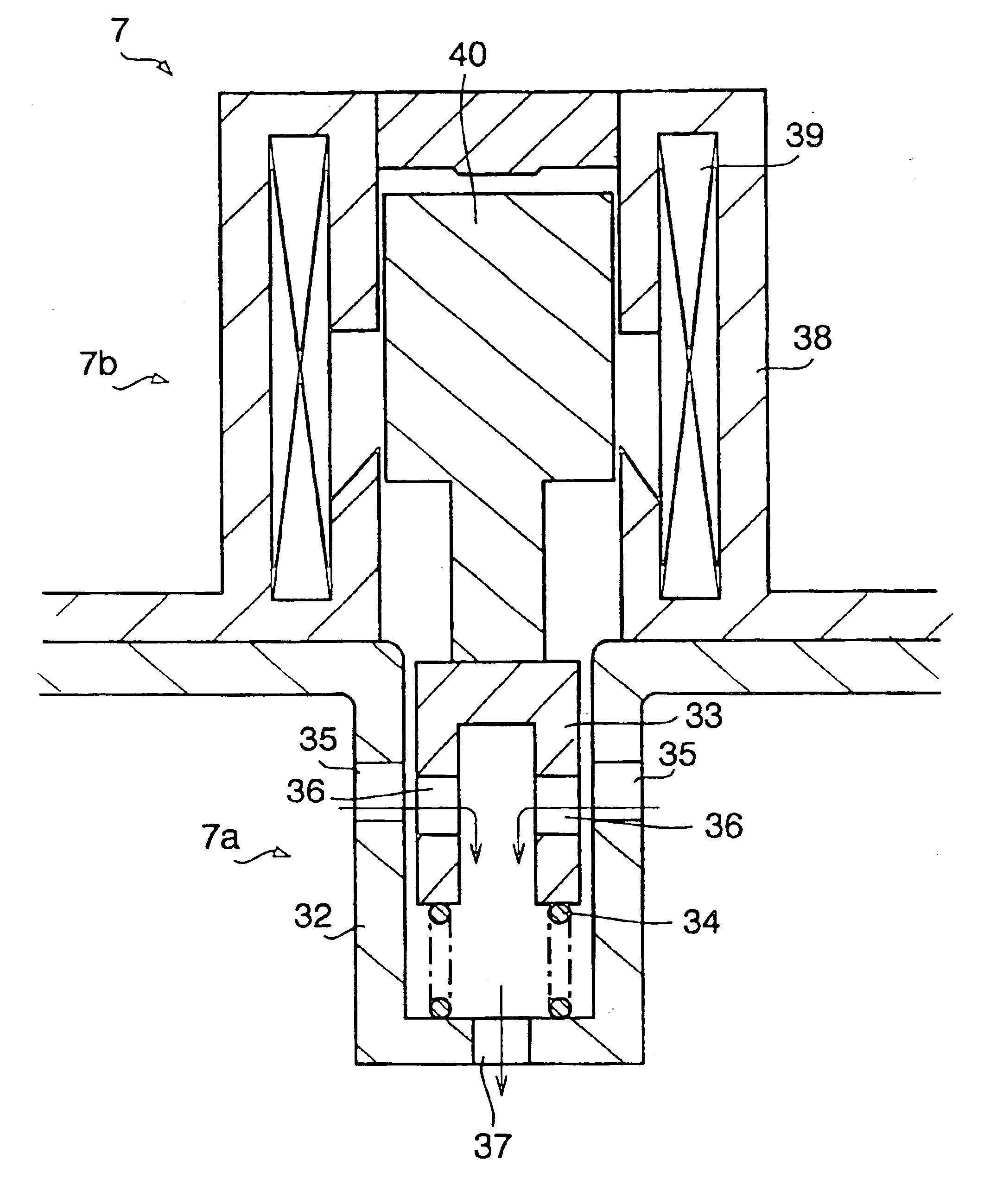
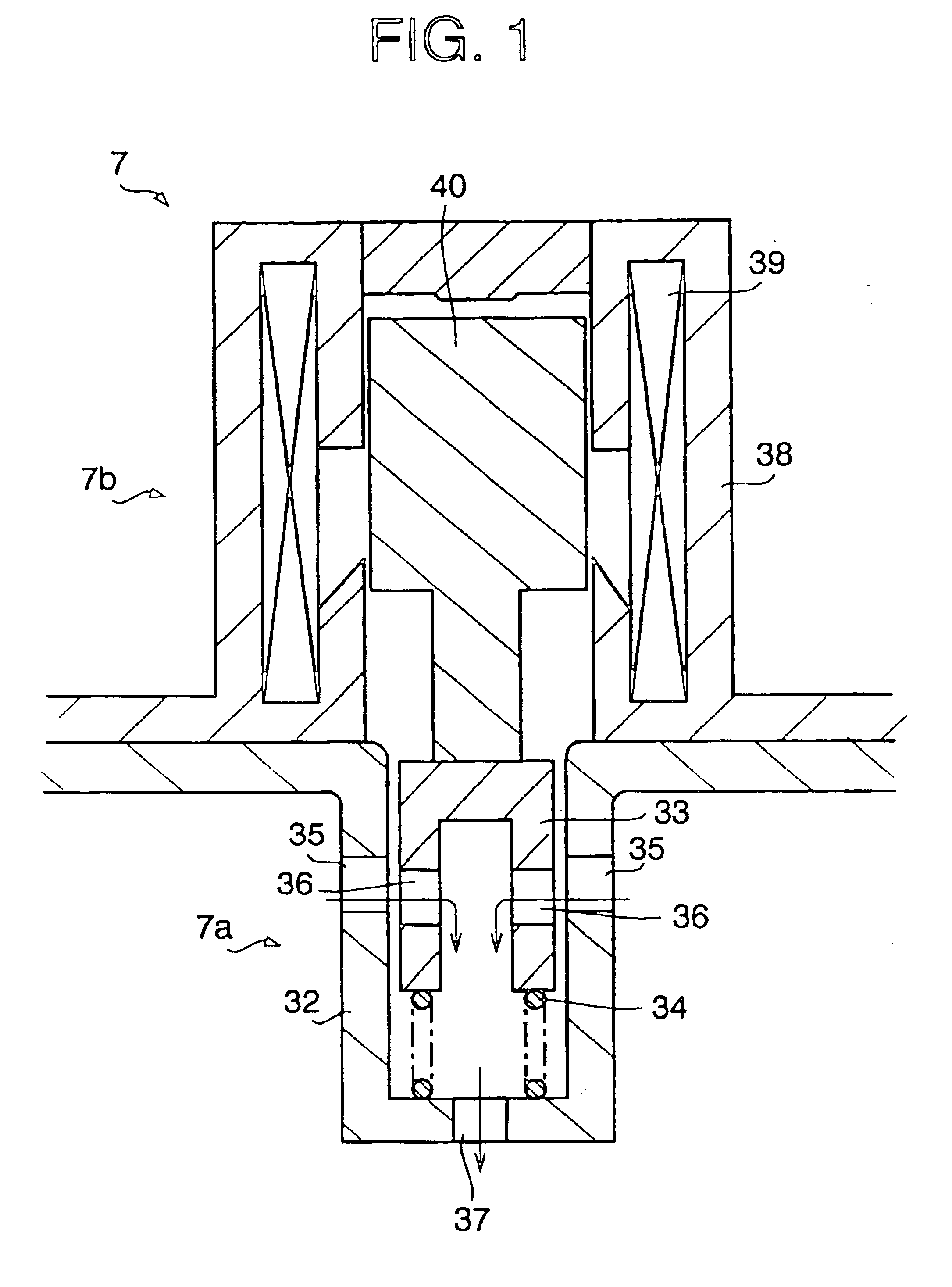
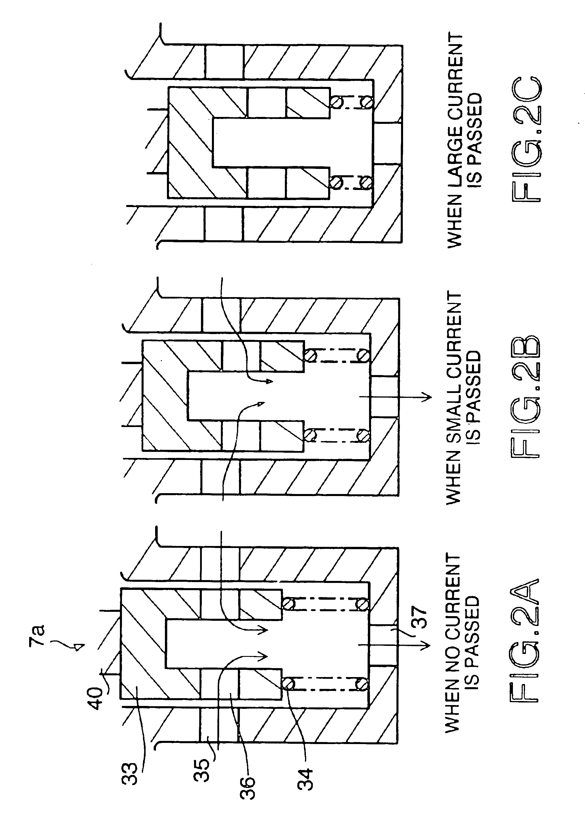
A metering valve 7 for adj...


PUM


Abstract

The common rail fuel injection control device in accordance with the present invention computes a base duty (A) equivalent to a base target opening degree of a metering valve and a correction coefficient (B) based on the engine operation state, adds the value obtained by multiplying an oscillation duty (C) which oscillates periodically by the correction coefficient (B) to the base duty (A), and determines the final duty (D) equivalent to a final target opening degree of the metering valve.

Description

CROSS REFERENCE TO RELATED APPLICATIONApplicants hereby claim foreign priority benefits under U.S.C. §119 of Japanese Patent Application No. 2002-362269, filed Dec. 13, 2002, and the content of which is herein incorporated by reference.BACKGROUND OF THE INVENTION1. Field of the InventionThe present invention relates to a common rail fuel injection control device suitable for diesel engines, more specifically to a method for controlling a metering valve for adjusting the quantity of fuel pumped into the common rail.2. Description of the Related ArtIn common rail fuel injection control devices for diesel engines, high-pressure fuel with a pressure increased to an injection pressure (for example, from several tens to several hundreds of MPa) is accumulated in a common rail at a pressure, and this fuel is injected into cylinders by opening the valves of injectors. As for fuel supply into the common rail, fuel pumping is conducted with a supply pump serving as a high-pressure pump, and t...

Claims


Application Information

Patent Timeline
Patent Type & Authority Patents(United States)
IPC IPC(8): F02M59/34F02M59/00F02M59/46F02M59/20F02D41/30F02D41/38F02D41/04F02D45/00F02M47/00F02M51/00
CPCF02D41/3809F02D41/3845F02M63/004F02M59/34F02M59/466F02D2041/2027F02D41/20
Inventor YOMOGIDA, KOICHIRONAKANO, FUTOSHISAIGO, YUSUKESASAKI, YUJI
Owner ISUZU MOTORS LTD
Why Eureka
Try Eureka