Linear permanent magnet drving system and permanent magnet driving and magnetic suspension roadway system

Inactive Publication Date: 2011-11-10
LIU ZHONGCHEN
View PDF6 Cites 41 Cited by
  • Summary
  • Abstract
  • Description
  • Claims
  • Application Information

AI Technical Summary

Benefits of technology

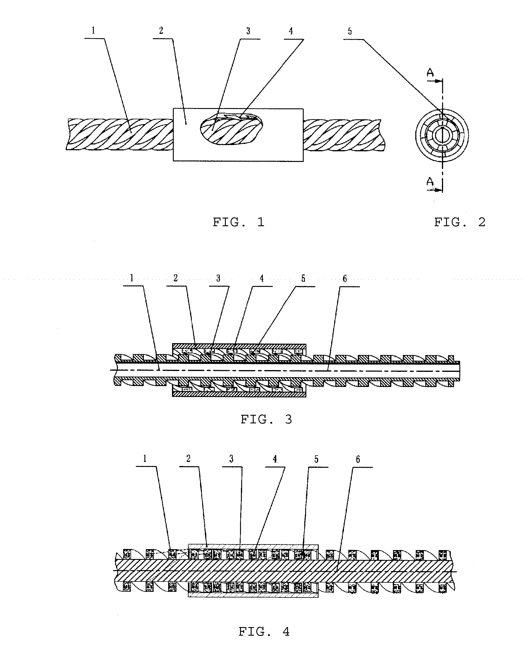
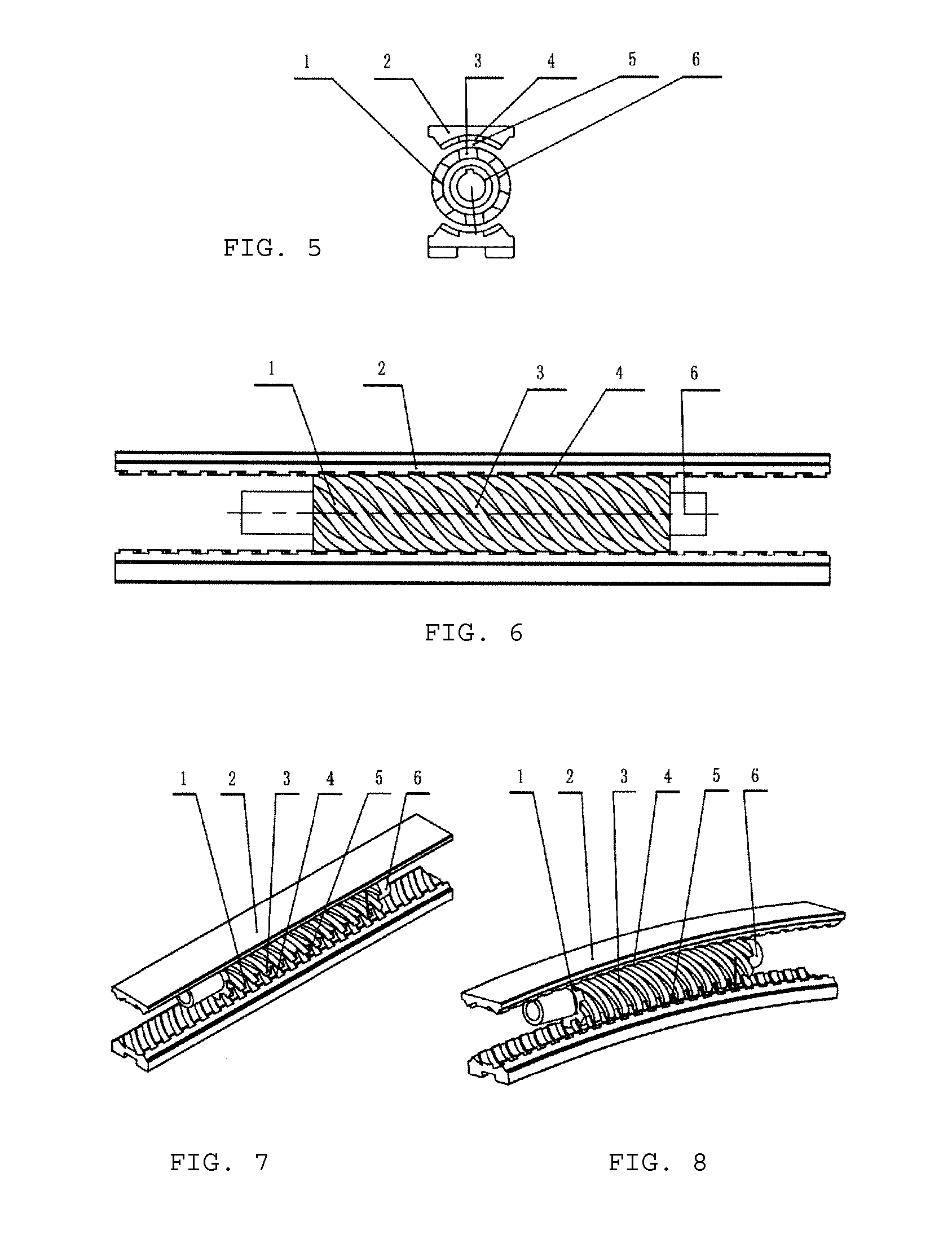
[0050]1. High transmission efficiency. Adopting permanent strong magnets for noncontact transmission, the linear permanent magnet driving system of the invention has almost no mechanical friction, no change of magnetic field, almost no generation of electromagnetic resistance and eddy current loss and almost no energy loss, transmission pairs consisting of the spiral rotors and the stators reach nearly 100% of the transmission efficiency, which is higher than the transmission efficiency of linear synchronous motor and linear induction asynchronous motor, and the entire transmission efficiency of the system is identical to that of rotating motor with the magnetic force gap ranging from 0.5 to 1.0 millimeter, so maximal effectiveness of prime motor can be brought into play.
[0063]3. The turnouts are structurally simple and easily controlled, the rail is firm and accurate in positioning and precise in jointing, as well as has not large bending deformational stress generated during switching, higher permissible traveling speed at the curved rail than deformational rail and longer service life, so the system is suitable for various rails with complex shape.

Problems solved by technology

High speed resulted from the open structure of wheels and rail requires extremely high planeness of the surface of rail, otherwise, even a tiny protrusion or particle could cause derailing and turnover of high-speed wheel / rail train, tragic derailing accidents of wheel / rail train and enormous casualties have been caused yearly over the years, resulting in vast economic loss.
The high-speed maglev levitation train having an EDS electric levitation system adopts the levitation and automatic guidance technique of cryogenic superconductive electromagnet and repulsion of coils of the rail, besides, the cryogenic superconducting technology by means of liquid nitrogen cryogenic refrigeration is also adopted, and the EDS technique has higher cost and larger noise than the EMS technique.
Rail aluminum plate and onboard permanent magnet system in Magplane maglev plane generate levitation repulsion during operation and can achieve automatic guidance, the control system is structurally simple, however, the use of thick aluminum plate in large quantities leads to higher cost of the rail, semi-arch-shaped rail is liable to result in transverse rolling of cars, what's more, tremendous electromagnetic resistance is generated between onboard permanent magnet and rail aluminum plate so as not to achieve the advantage of saving energy.
Being levitated with the rail entirely, the maglev train obtains quite small frictional resistance of traveling, so the difficult problem of how to achieve fast driving between the maglev train and the rail is generated while extremely high speed is reached.
In order to accurately control the crest synchronization of train and electromagnetic driving, quite advanced synchronous linear motor technology is needed, and considerable investment is required by the construction of power distribution stations along the rail owing to the rail-side long stator sectional power supply and cloth-changing feeding technology, however, the high cost of synchronous linear motor driving rail for high-speed maglev train is prohibitive to nations, which, therefore, cannot achieve extensive population of this technology.
Too small distance between the maglev train and the rail could bring large difficulties to manufacturing and construction, so as to enhance manufacturing cost and arouse unsafe traveling.
And too large distance could lead to obvious efficiency reduction of synchronous linear motor, the maximal acceptable levitation height, limited by the efficiency of linear motor, is maintained at about 8 to 12 millimeters.
However, the distance between train stator and induction board during traveling is about 10 to 12 millimeters, which is far larger than the gap, i.e. 0.5 to 1.0 millimeters, between stator and rotor of rotating motor, thereby resulting in lower power factor and efficiency, i.e. only 0.5-0.7 typically, and large excitation power consumption causes higher heat loss and electromagnetic radiation loss of motor equipment and even lower power factor and efficiency in case of high speed, therefore, the development of the maglev train adopting this technology toward high speed is limited and the maglev train is only suitable for traveling at low speed below 120 kilometer per hour.
The induction boards on the rail, which are made of aluminum plate in large quantities, lead to high cost of the entire rail.
The current magnetic levitation technology still has the problem of being non-compatible with common rail and is accordingly free from universality, networkability and compatibility in modern transportation.
It is the laying of aluminum coils on the rail or the use of thick aluminum plates in large quantities as required by the current high-speed maglev train driving way that leads to considerable cost of the entire rail to further make maglev technology inaccessible, and the short stator linear induction motor of low-speed maglev train is low in driving efficiency, so cost and efficiency of noncontact driving technology become a determining factor for the future of maglev technology, in case that the noncontact linear driving technology characterized by high driving efficiency, powerful driving force and low cost appears and lowers the construction cost of maglev train rail to be almost equal to that of high-speed wheel / rail, the maglev train is endowed with incomparable superiors and will become one of the most promising transportation means in the future.
1. In the aspect of energy and power saving, in addition to the energy and power saving effect resulted from permanent magnet driving, train levitation is achieved by the permanent magnet levitation technology in which almost no power is consumed, so the maglev train can save energy several times as much as common wheel / rail train and save energy by 60% to 90% compared with subway train and light rail train in case of low speed traveling, conforming to the policy of energy conservation and pollution reduction.
2. Low total construction cost of the rail. It is possible for the entire rail to be made of low-cost steel materials without permanent strong magnets, driving copper or aluminum coils on the rail and aluminum plates in large quantities, therefore, the construction cost of the rail is quite low, equivalent to the construction cost of high-speed wheel / rail. The construction of both control power station divisions along the rail and complex control electrical systems is avoided, so the construction cost along the rail is low. High processing accuracy of the iron cores of the spiral stators on the rail is not required owing to large gap of transmission magnetic force, so the manufacturing process is simple and the manufacturing cost is low. As a result of that, the total construction cost of the linear permanent magnet driving maglev train rail is lowered to the level equivalent to the construction cost of high-speed wheel / rail, which will remarkably promote the popularization and generation of magnetic levitation technology.
3. The turnouts are structurally simple and easily controlled, the rail is firm and accurate in positioning and precise in jointing, as well as has not large bending deformational stress generated during switching, higher permissible traveling speed at the curved rail than deformational rail and longer service life, so the system is suitable for various rails with complex shape.
4. Great universality. The system overcomes the non-compatibility problem between the maglev train and the existing rail transportation system, and can accordingly, realize the interchangeability of maglev rail and common rail, i.e. both the maglev train at high speed and the common wheel / rail train at low speed can travel on the permanent magnet driving levitation rail, the wheel / rail train can also travel on the maglev rail temporally, the maglev train equipped with double-driving system not only can travel at normal speed on common rail, but can also travel at high speed on the permanent magnet driving levitation rail, leading the maglev rail to universality, networkability and compatibility in transportation. Modernized scheduling system and human-computer engineering system same as the rail control system can be used as operation scheduling system.

Method used


Image

  • Linear permanent magnet drving system and permanent magnet driving and magnetic suspension roadway system
  • Linear permanent magnet drving system and permanent magnet driving and magnetic suspension roadway system
  • Linear permanent magnet drving system and permanent magnet driving and magnetic suspension roadway system

Examples


embodiment 1

Viaduct Hanger Rail-Type Permanent Magnet Driving Maglev Train

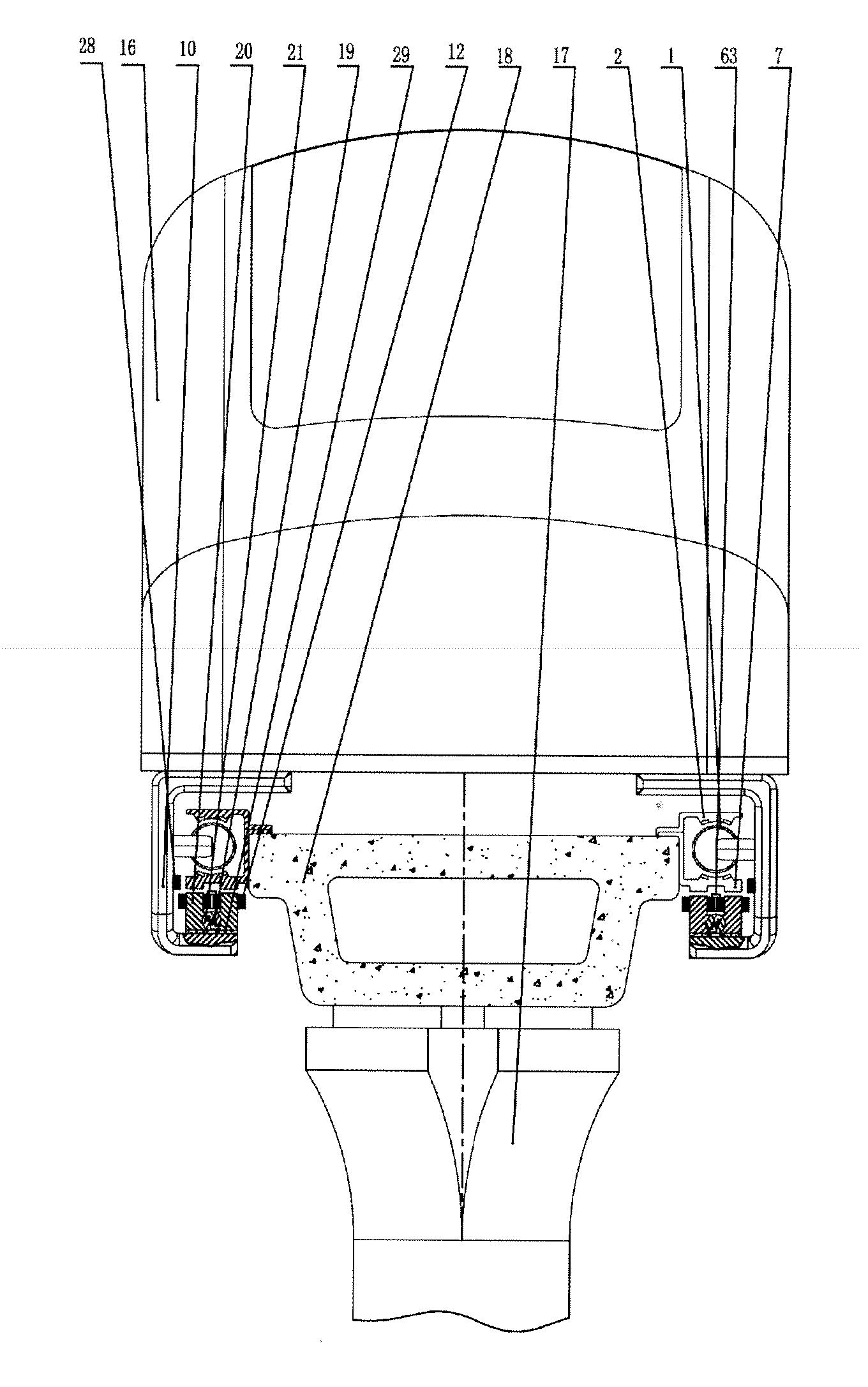
[0122]Shown as FIG. 26, a concrete viaduct cross beam 18 is laid on a concrete pier 17, the bottom of the concrete viaduct cross beam 18 is fixedly connected with the spiral stator 2 which is coaxial with the spiral rotor 1, the spiral stator is bushing-shaped with an opening facing downwards and is formed, in a manner of extending downwards, with an integrated structure of a groove positioning rail and a magnetically conductive armature 7 at the opening.

[0123]The spiral rotor 1 is connected with a vehicle body 16 via a connecting arm 10, the connecting arm 10 is provided with a U-shaped iron core 20, a middle transverse bridge of the U-shaped iron core 20 is embedded with a permanent magnet adjustment device, namely the middle part is grooved for the installation of a cylindrical rotating shaft 21 of a permanent magnet 19, the end part where the U-shaped iron core 20 is corresponding to the armature 7 is provided with el...

embodiment 2

Low-Speed Underground Rail Maglev Airbus

[0127]Shown as FIGS. 28 to 30, an underground hole 24 is arranged below a roadbed 23 of bus line. The underground hole 24 is internally provided with a linear permanent magnet driving system, a permanent magnet levitation system capable of adjusting levitation suction, a guide wheel safety system and a electromagnetic auxiliary control system, a maglev airbus body 16 is supported by a quite long connecting arm 10 to aerially travel at 2 meters above the ground, i.e. the airbus, the airbus body 16 is connected with a spiral rotor 1 through the connecting arm 10. Car, jeep and other small locomotives can travel in the space at the bottom of the airbus, and parking and traveling of the airbus causes no hindrance to passage of other vehicles, thus barrier-free parking can be realized.

[0128]The airbus is driven by the linear permanent magnet driving system arranged inside the underground hole 24, and levitation thereof is implemented and controlled...

embodiment 3

Viaduct Encircling Maglev Train

[0133]Shown as FIG. 31, the viaduct encircling maglev train is characterized in that, a concrete viaduct cross beam 18 is laid above a concrete viaduct pier, left and right sides of the concrete viaduct cross beam 18 are fixedly connected with spiral stators 2, which is similar to the above maglev airbus, spiral rotors 1 arranged concentrically with the spiral stators 2 are connected with a train body 16 through connecting arms 10, the connecting arms 10 are provided with H-shaped iron cores 20; the difference from the maglev airbus is that this structure further comprises an electromagnetic auxiliary control system, i.e. levitation-assistant electromagnetic coils 12 and guidance-assistant electromagnetic coils 28 are mainly related to; the levitation-assistant electromagnetic coils 12 are installed on the iron cores 20 of the permanent magnet levitation system in vertical correspondence to armatures 7; displacement sensors 63 are installed on the conn...


PUM


Abstract

The invention relates to a linear permanent magnet driving system and a permanent magnet driving maglev train rail system, the linear permanent magnet driving system comprises spiral rotors and stators, wherein at least one of the spiral rotor and the stator adopts the structure having a permanent magnet while the other one adopts the structure having the permanent magnet or a magnetizer; when the spiral rotors are driven by an engine to rotate, linear motion of the spiral rotors is achieved by means of the magnetic force between both, and speed of the linear motion of the spiral rotors can reach supersonic speed at most. By applying the linear permanent magnet driving system to the permanent magnet driving maglev train rail system, the entire rail can avoid the use of both permanent magnet and driving coil, and the construction cost of maglev train rail is equivalent to that of the current high-speed wheel / rail. The permanent magnet driving maglev train can save energy by 60 to 90% compared with wheel / rail train when traveling at low speed below 80 kilometers per hour and save energy by about 50% compared with high-speed wheel / rail train when traveling at high speed above 200 kilometers per hour. The invention can realize the interchangeability of maglev rail and common rail, leading the maglev rail to universality, networkability and compatibility in modern transportation.

Description

TECHNICAL FIELDS[0001]The invention relates to the technical field of noncontact magnetic force transmission and permanent magnet levitation train, specifically to a linear permanent magnet driving system and a permanent magnet driving maglev train rail system, especially a permanent magnet linear driving maglev train.BACKGROUND ARTS[0002]Throughout the development history of railway locomotive, railway locomotive has been transformed for generations since the birth, and accordingly, tremendous changes have occurred, from steam locomotive, diesel locomotive and electric locomotive on wheel / rail to maglev train. The wheel / rail train has a long history but simple and mature technique. High speed resulted from the open structure of wheels and rail requires extremely high planeness of the surface of rail, otherwise, even a tiny protrusion or particle could cause derailing and turnover of high-speed wheel / rail train, tragic derailing accidents of wheel / rail train and enormous casualties ...

Claims


Application Information

Patent Timeline
Patent Type & Authority Applications(United States)
IPC IPC(8): B60L13/10E01B25/34H02K49/10
CPCB60L13/003B60L13/10B60M7/00B60L2200/26H02K49/102H02K49/106H02K7/06
Inventor LIU, ZHONGCHEN
Owner LIU ZHONGCHEN
Why Eureka
Try Eureka