Flow sensing fuel system

a fuel system and flow sensing technology, applied in the field of fuel systems, can solve the problems of gross seat leakage conditions that cannot be eliminated completely, the inability to detect the hydrostatic lock caused by large fuel leakage in one or more cylinders of the engine, and the inability to eliminate gross seat leakage conditions completely, so as to reduce the noise and fuel metering variations within a given injector and reduce the effect of fuel leakage into the external environmen

Inactive Publication Date: 2009-10-08
DELPHI TECH INC
View PDF30 Cites 38 Cited by
  • Summary
  • Abstract
  • Description
  • Claims
  • Application Information

AI Technical Summary

Benefits of technology

[0011]By including the monitoring device, the fuel pressure sensor, and the controllable pressure regulator in the fuel system of a gasoline or diesel engine, identification of an injector malfunction, such as a stuck open or gross seat leakage condition or fuel leakage to the external environment is enabled during engine start-up, during engine operation, and after engine...

Problems solved by technology

Drawbacks of the prior art include, for example, that a hydraulic lock caused by large fuel leakage in one or more cylinders of the engine currently cannot be detected after engine shut down.
Hydraulic lock of an engine is typically caused by a stuck open condition or a gross seat leakage condition of one or multiple injectors causing a volume of unwanted and incompressible fuel to accumulate in the combustion chamber.
However, under current manufacturing processes stuck open or gross seat leakage conditions cannot be eliminated completely.
As a result, engine damage due to stuck op...

Method used


Image

  • Flow sensing fuel system
  • Flow sensing fuel system
  • Flow sensing fuel system

Examples


Embodiment Construction

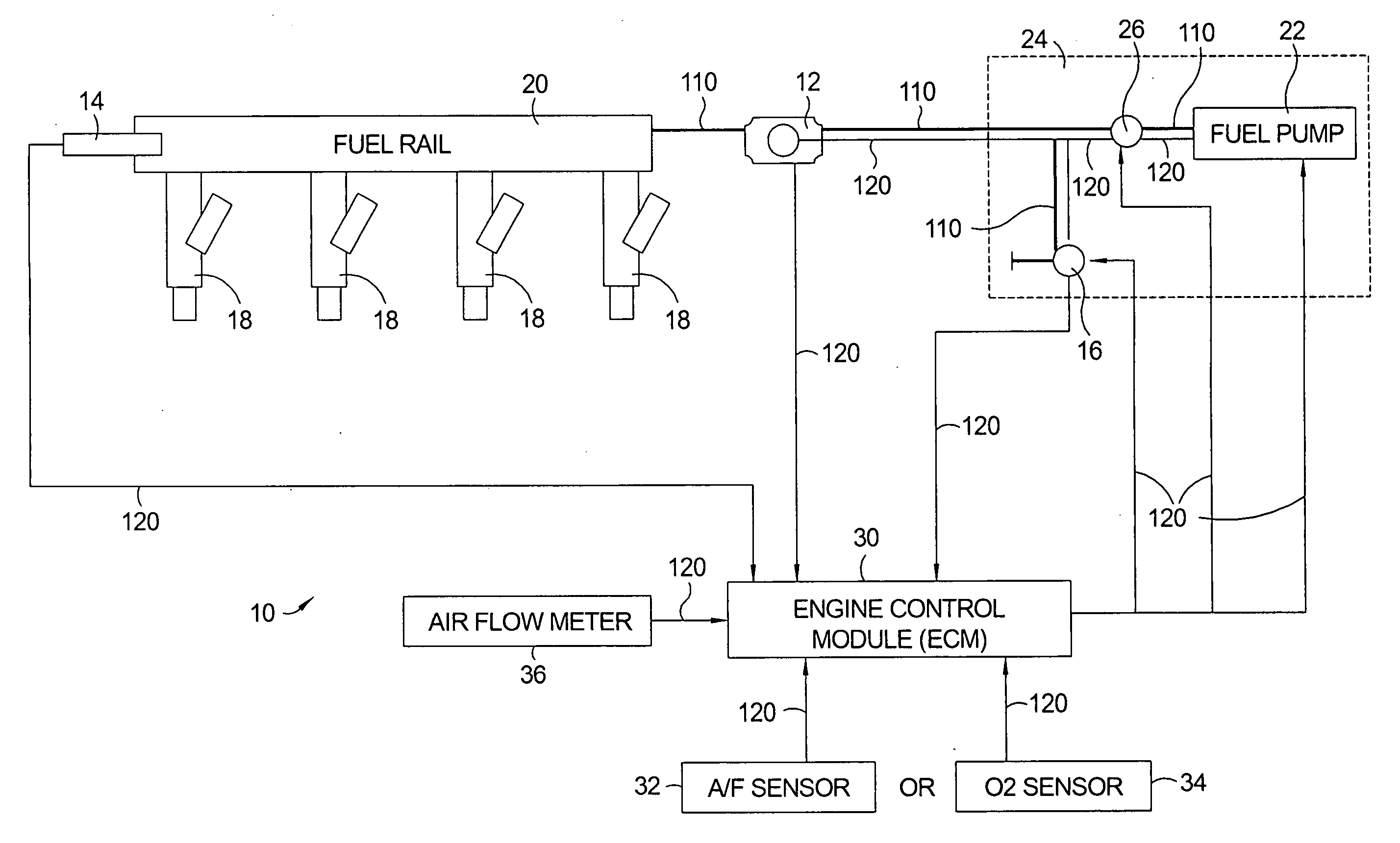
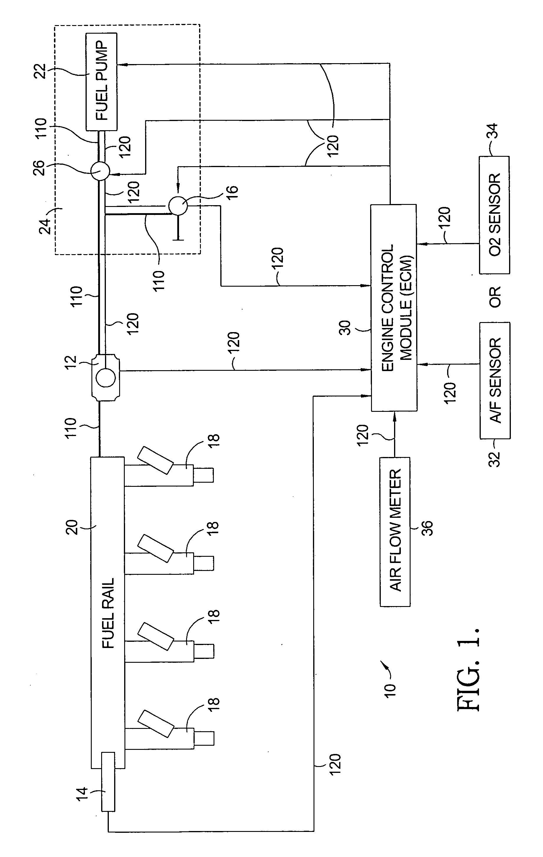
[0020]Referring to FIG. 1, a flow sensing fuel system 10 for MPFI engine applications includes a flow monitoring device 12, a fuel pressure sensor 14, and a controllable pressure regulator 16 as additional elements of a current commercial fuel system. To supply fuel to an MPFI engine (not shown) multiple injectors 18 are included in the fuel system 10. The fuel inlet of each injector 18 is connected to a fuel rail 20. Fuel is pumped by a fuel pump 22 from a fuel tank 24 to fuel rail 20. A controllable check valve 26 in fuel tank 24 may be included to control the fuel flow supplied by fuel pump 22. Flow monitoring device 12 is positioned in the flow passage between fuel pump 22 and fuel rail 20 and monitors the fuel flow from fuel pump 22 to fuel rail 20. Fuel pressure sensor 14 is in fluid communication with fuel rail 20 and monitors the fuel pressure in fuel rail 20. Flow monitoring device 12 and fuel pressure sensor 14 provide input data lo to an engine control module (ECM) 30. Th...


PUM


Abstract

A flow sensing fuel system for multiple port fuel injection gasoline engines, gasoline direct injection engines, or common rail diesel engines include a flow monitoring device positioned in a fuel flow passage between a fuel pump and a fuel rail, a fuel pressure sensor in fluid communication with said fuel rail, and a controllable pressure regulator closing to a fuel tank. By integrating flow monitoring device, fuel pressure sensor, and controllable pressure regulator in existing fuel systems, a flow sensing fuel system is provided that protects the engine and limits the fuel leaking into the environment in case of a stuck open condition or sealing problem of one or more injectors or in case of a leak in the fuel rail assembly. The flow sensing fuel system enables monitoring the fuel flow during engine start-up, during engine operation, and after engine shut down.

Description

TECHNICAL FIELD[0001]The present invention relates to fuel systems for spark ignited and compression ignited engines; more particularly, to multiple port fuel injection (MPFI) and gasoline direct injection (GDI) fuel systems for spark ignited engines and common rail fuel systems for compression ignited engines with closed loop control; and most particularly, to a flow sensing fuel system and method for monitoring the fuel flow in a fuel system under real time engine conditions.BACKGROUND OF THE INVENTION[0002]Multiple port fuel injection (MPFI) and gasoline direct injection (GDI) fuel systems for spark ignited engines and common rail fuel systems for compression-ignited engines with closed loop control are well known. Engine management systems (EMS) of such prior art internal combustion engines typically include a fuel injection system (also referred to herein simply as fuel system), an emission diagnostic system, and an air flow meter that all interact with a powertrain control mod...

Claims


Application Information

Patent Timeline
IPC IPC(8): F02D1/00F02M69/54G06F19/00
CPCF02D41/22F02D41/3836F02D2041/224F02M69/54F02D2200/0614F02M63/0245F02D2041/225
Inventor XU, WENBINSHEBERT, LEONARD L.SOFIANEK, JAY K.
Owner DELPHI TECH INC
Why Eureka
Try Eureka