Vent stringer and aircraft main wing

Active Publication Date: 2012-07-26
MITSUBISHI AIRCRAFT
View PDF2 Cites 7 Cited by
  • Summary
  • Abstract
  • Description
  • Claims
  • Application Information

AI Technical Summary

Benefits of technology

[0019]According to the present invention, the rib and the cover can be fastened to each other on the wing inside of the wing panel. Thereby, since the fastening members such as rivets are not exposed to the outer surface of the wing, a spark can be prevented from occurring in a fuel tank in the wing through the fastening member at the time of a lightning strike. Since the mating surface of the rib and the cover is also separate from the outer surface of the wing to the inside of wing, a spark is less liable to occur even in the case where the rib and the cover are formed of independent parts. Thus, lightning protection capability can be improved significantly.
[0020]Also, since the work for fastening the cover to the rib using

Problems solved by technology

Unfortunately, the above-described configuration has a problem in terms of lightning protection.
Also, the fastening work using the rivets 4 must be performed on the inner peripheral surface 2a side and the outer peripheral surface 2b side of the wing panel 2, for example, in such a manner that a rivet material is inserted from the outer peripheral surface 2b side of the wing panel 2, and the bucking is performed on the inner

Method used


Image

  • Vent stringer and aircraft main wing
  • Vent stringer and aircraft main wing
  • Vent stringer and aircraft main wing

Examples


Example

[0029]The present invention will now be described in detail based on an embodiment shown in the accompanying drawings.

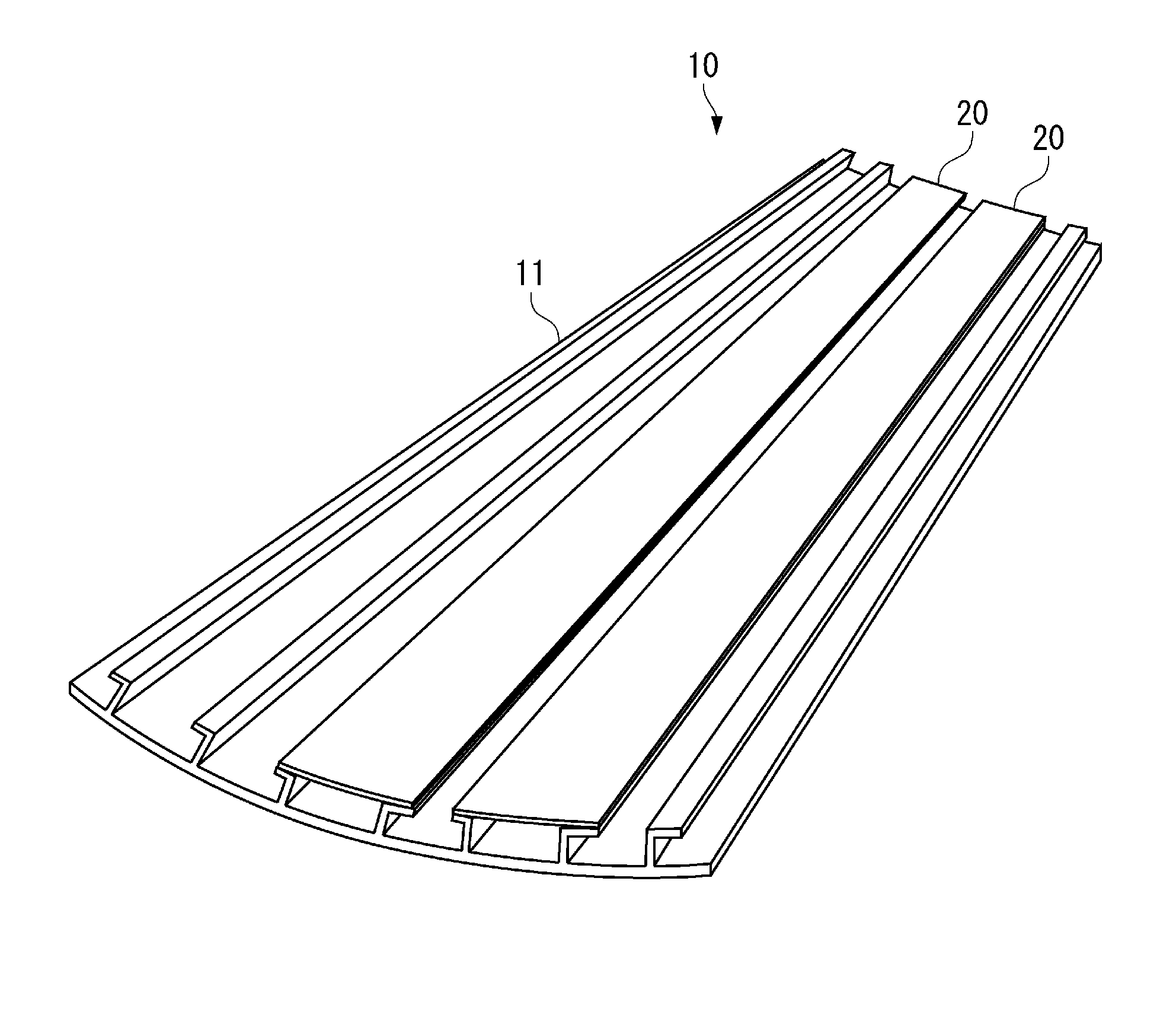
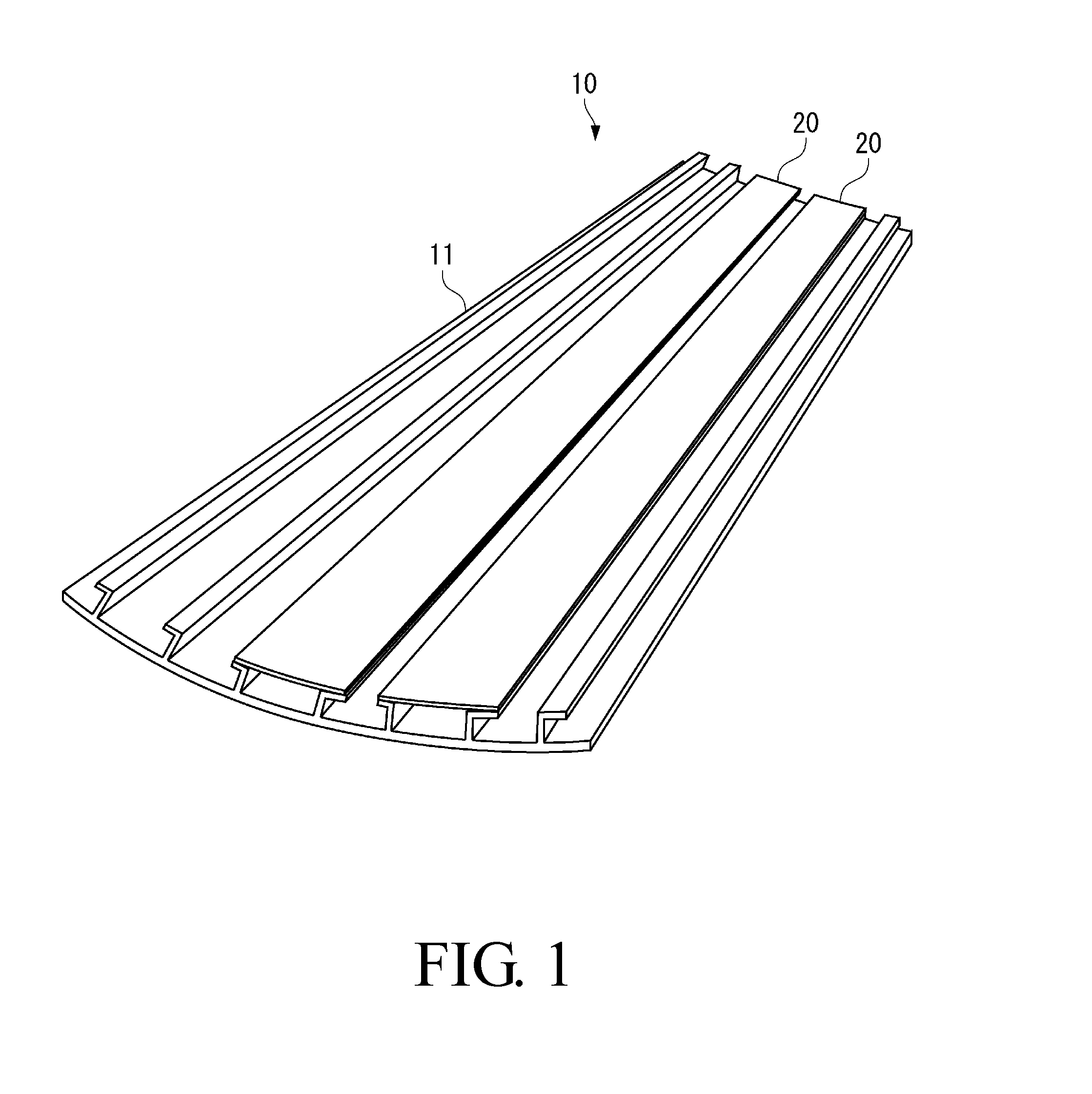
[0030]FIG. 1 is a perspective view of a wing panel 11 constituting an aircraft main wing 10 in accordance with the embodiment.

[0031]As shown in FIG. 1, the main wing 10 includes the wing panel 11 forming the wing surface on the upper surface side of the main wing 10, and vent stringers 20 provided in the main wing 10.

[0032]In this embodiment, the main wing 10 is configured so that the upper surface side thereof is formed by one wing panel 11. However, the configuration is not limited to this one, and two or more wing panels 11 may be combined to form the upper surface side of the main wing 10.

[0033]The vent stringers 20 are provided so as to be continuous along the spanwise direction of the main wing 10 and to be parallel with each other.

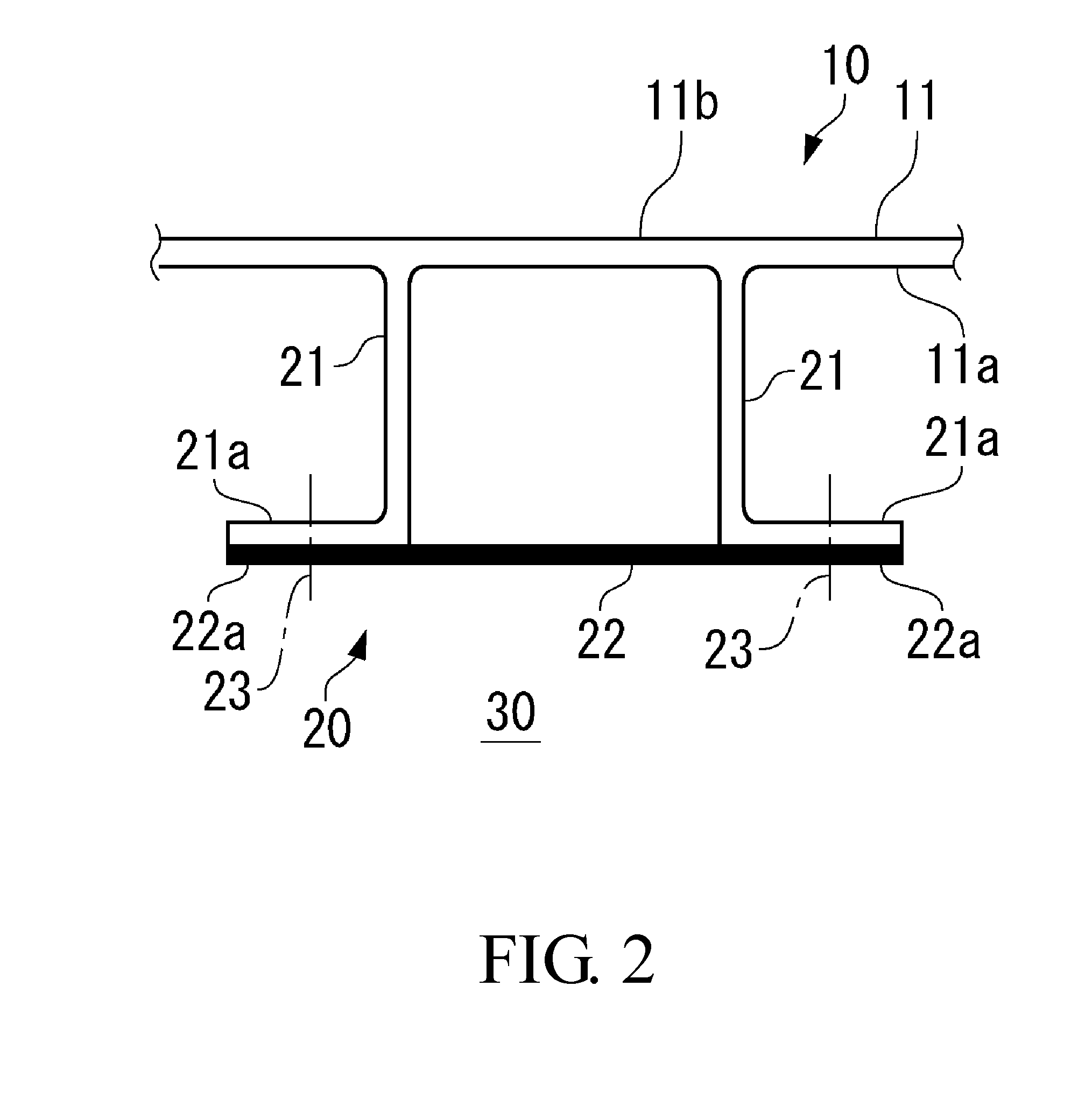
[0034]As shown in FIG. 2, each of the vent stringers 20 is formed by a pair of ribs 21 rising toward the direction perpendicular to...


PUM


Abstract

A vent stringer 20 is formed by a pair of ribs 21 rising in the direction perpendicular to an inner surface 11a of a wing panel 11, and a cover 22 provided in the tip end portions of the ribs 21. With rivets 23 unexposed to an outer surface 1 lb of the wing panel 11, a spark is prevented from occurring in a fuel tank 30, which is provided in a main wing 10, through the rivet 23 at the time of a lightning strike. Formed by being machined integrally with the wing panel 11, the rib 21 is formed with high accuracy so as to match the curved shape of the wing panel 11. The cover 22 has only to be formed by curving a strap member so as to match the shapes of the wing panel 11 and the ribs 21.

Description

BACKGROUND OF THE INVENTION[0001]1. Field of the Invention[0002]The present invention relates to a vent stringer provided in an aircraft main wing and the aircraft main wing.[0003]2. Description of the Related Art[0004]A fuel tank is provided in an aircraft main wing. Also, in the main wing, a vent member for introducing air from the outside into the fuel tank is provided to prevent the pressure in the tank from becoming negative when the amount of fuel in the fuel tank is decreased. The vent member also has a function of preventing the interior of the tank from becoming overpressurized at the time of refueling on the ground. The vent member has an air introducing duct on the outside of the main wing, and supplies air, which is taken in through this air introducing duct, into the fuel tank.[0005]The vent member is provided so as to be continuous along the spanwise direction of the main wing on the inner peripheral surface side of a wing panel forming the outer surface of the main wi...

Claims


Application Information

Patent Timeline
IPC IPC(8): B64C3/18B64D37/06B64D45/02B64D37/04
CPCB64D37/06B64C3/182
Inventor MOTOHASHI, HIDETOHOSOKAWA, YOSHIFUMIFUJII, TOSHINARIFUKUOKA, TOSHIYASU
Owner MITSUBISHI AIRCRAFT
Why Eureka
Try Eureka