Cogeneration apparatus

Active Publication Date: 2012-07-26
HONDA MOTOR CO LTD
View PDF0 Cites 10 Cited by
  • Summary
  • Abstract
  • Description
  • Claims
  • Application Information

AI Technical Summary

Benefits of technology

[0021]Turning the adjustment boss causes the crankshaft to turn and positions the piston at a top dead center. In this state, the intake valve and the exhaust valve are closed, and the gap between the valve shafts and the rocker arms (i.e., the tappet clearance) can be readily adjusted.
[0022]Desirably, the channel inlet of the ventilation-introducing channel and the channel outlet of the ventilation-introducing channel are both set to have a fixed cross-sectional channel area. Pressure losses in

Problems solved by technology

Accordingly, the noise when driving the fans (i.e., the noise accompanying ventilation) increases when the ventilation fan and the radiator fan are increased in size.
Mo

Method used


Image

  • Cogeneration apparatus
  • Cogeneration apparatus
  • Cogeneration apparatus

Examples


Embodiment Construction

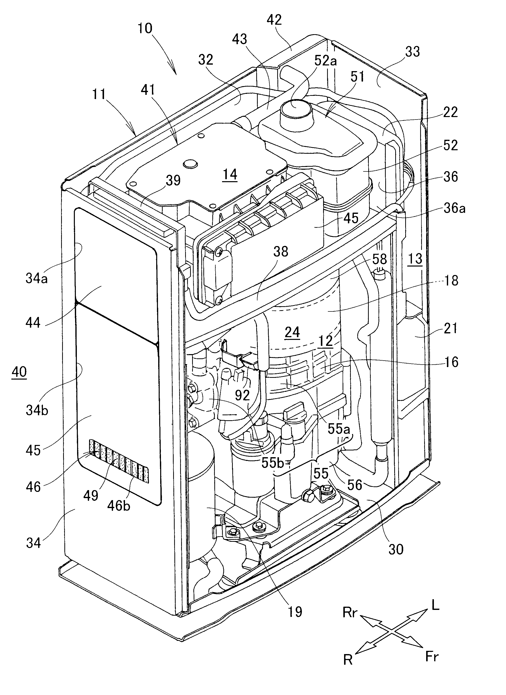
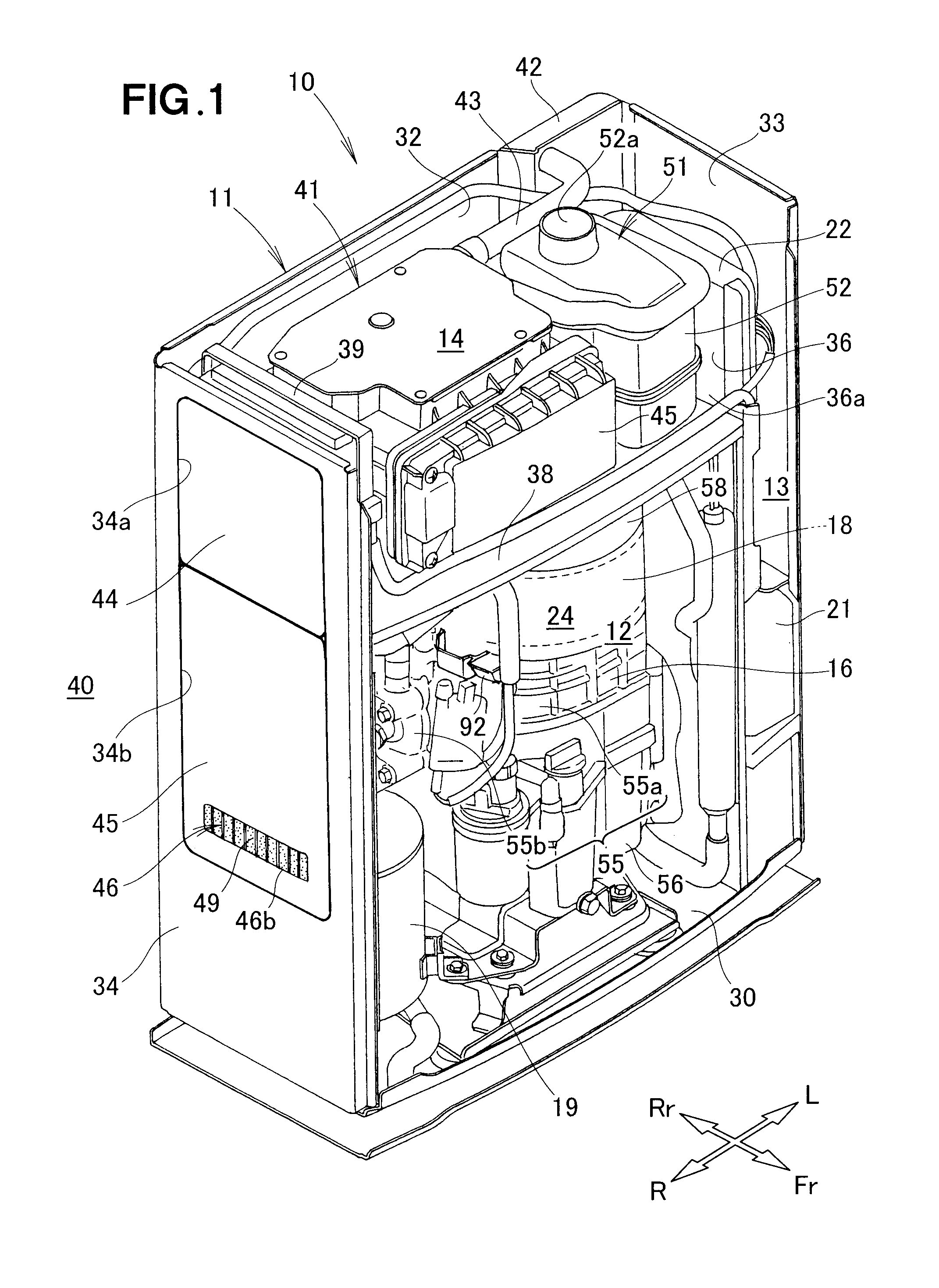
[0037]Throughout the description made as to the embodiment of the present invention with reference to the accompanying drawings, reference characters “Fr,”“Rr,”“L,” and “R” are used to represent “front,”“rear,”“left,” and “right”, respectively.

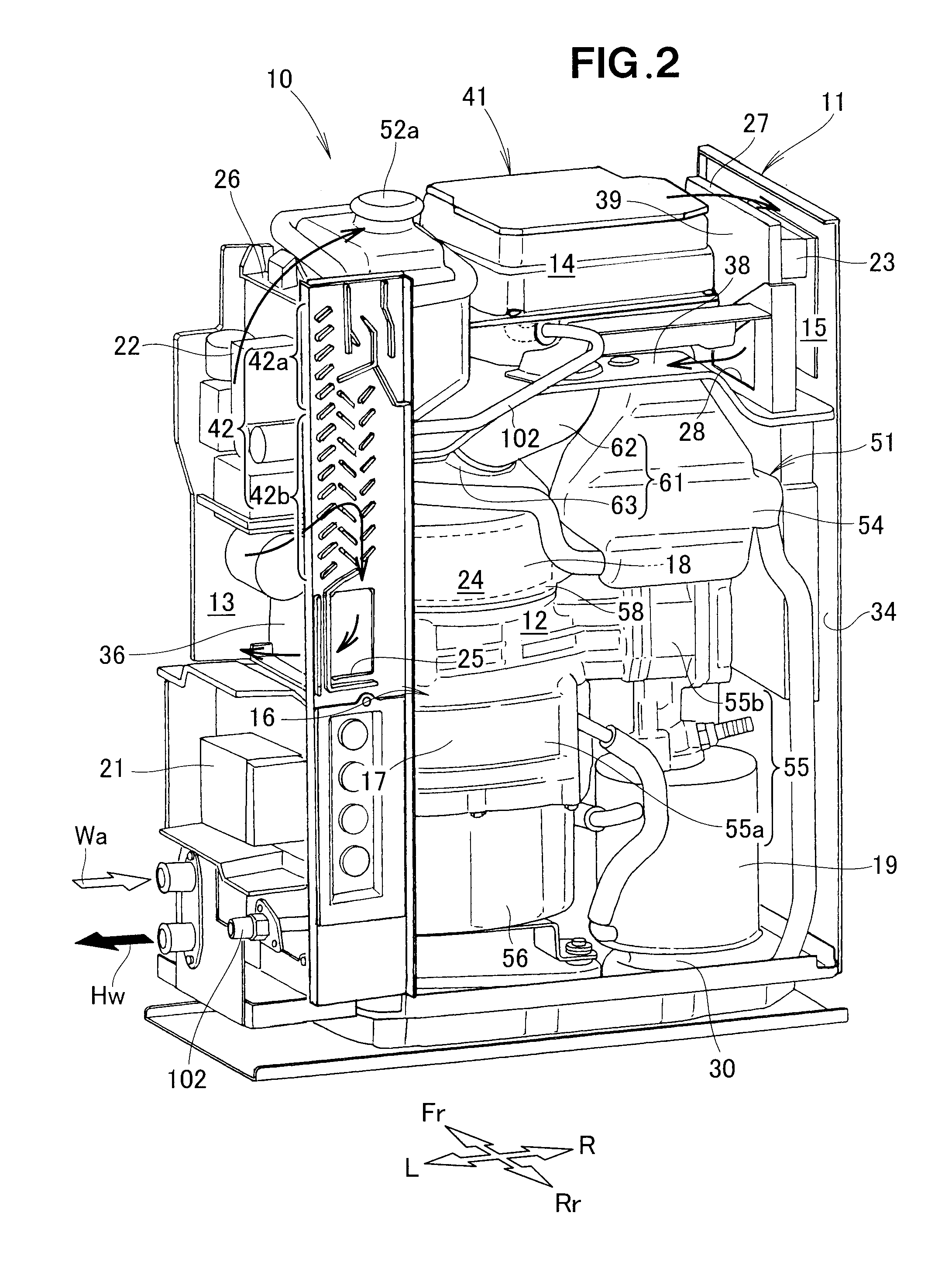
[0038]As shown in FIGS. 1 and 2, a cogeneration apparatus 10 is a combined heat-and-power apparatus that is provided with a cogeneration case (housing) 11, an engine (motor) 16 that is accommodated within the cogeneration case 11, an electrical generator 18, a heat exchanger 19, a first control part 21, a second control part 23, and a power converter part 22.

[0039]The cogeneration case 11 is formed into a substantially rectangular shape by a bottom part 30, a front panel (not shown), a rear panel 32, a left side panel 33, a right side panel 34, and a roof panel (not shown), whereby an interior space 24 is formed. An upper-panel aperture part 34a and a lower-panel aperture part 34b are formed in the right side panel 34. The right side panel 34 ...


PUM


Abstract

A cogeneration apparatus having a ventilation-introducing channel communicating an electrical-equipment compartment with a ventilation fan is disclosed. Driving the ventilation fan causes air to be led from an exterior of a cogeneration case through the electrical-equipment compartment to the interior of the ventilation-introducing channel. The air led to the interior of the ventilation-introducing channel is led to an electrical generator. The air led to the electrical generator is exhausted through a power-generation compartment to the exterior of the cogeneration case.

Description

FIELD OF THE INVENTION[0001]The present invention relates to a cogeneration apparatus capable of driving a ventilation fan to thereby ventilate the interior of a housing, and cooling electrical components, an electrical generator, and a motor.BACKGROUND OF THE INVENTION[0002]A well-known example of a cogeneration apparatus is disclosed in Japanese Patent Application Laid-Open Publication No. 2006-9678 (JP 2006-9678 A), in which an engine compartment is partitioned off within a housing (referred to as a “cogeneration case” below); an engine, an electrical generator, and a heat exchanger are provided to the engine compartment; and a ventilation fan and a radiator fan are provided for ventilating the engine compartment. Specifically, the interior of the cogeneration case is partitioned into the engine compartment, a duct compartment, a radiator compartment, and the like; and the engine, the electrical generator, and the heat exchanger are provided to the engine compartment. The ventila...

Claims


Application Information

Patent Timeline
IPC IPC(8): F02B65/00
CPCF02B63/04H02K5/20H02K7/1815Y02E20/14H02K11/046Y02T10/16H02K9/06Y02T10/12H02K5/207H02K11/05
Inventor TAKITA, YOSHIHARUNAOI, ATSUMU
Owner HONDA MOTOR CO LTD
Why Eureka
Try Eureka