Eureka AIR delivers breakthrough ideas for toughest innovation challenges, trusted by R&D personnel around the world.

Method for detecting deterioration of permanent magnet in electric motor and system for the method

a technology of permanent magnet and electric motor, which is applied in the direction of motor/generator/converter stopper, electronic commutator, dynamo-electric converter control, etc., can solve the problems of electric motor mounted in a vehicle and repeating stop and start operations, and the technology for detecting the deterioration of a permanent magnet in a rotor of an electric motor has not been established

Inactive Publication Date: 2012-07-26
TOYOTA IND CORP
View PDF17 Cites 8 Cited by
  • Summary
  • Abstract
  • Description
  • Claims
  • Application Information

AI Technical Summary

Benefits of technology

The present invention provides a method for detecting deterioration of a permanent magnet in an electric motor with multi-phase coils and a rotor that incorporates the permanent magnet. This is done by measuring the peak currents during the starting of the motor and comparing them to determine if the permanent magnet is deteriorated. The invention also includes a system for detecting deterioration of a permanent magnet in an electric motor using an electric motor, an inverter circuit, a current sensor, and a controller. The technical effect of the invention is to provide a reliable and efficient way to detect deterioration of a permanent magnet in an electric motor, which can help to prolong the life of the motor and prevent damage or malfunctions.

Problems solved by technology

However, a technology for detecting the deterioration of a permanent magnet in a rotor of an electric motor has not been established.
However, an electric motor which is mounted in a vehicle and repeats stop and start operations has not been developed yet.

Method used


Image

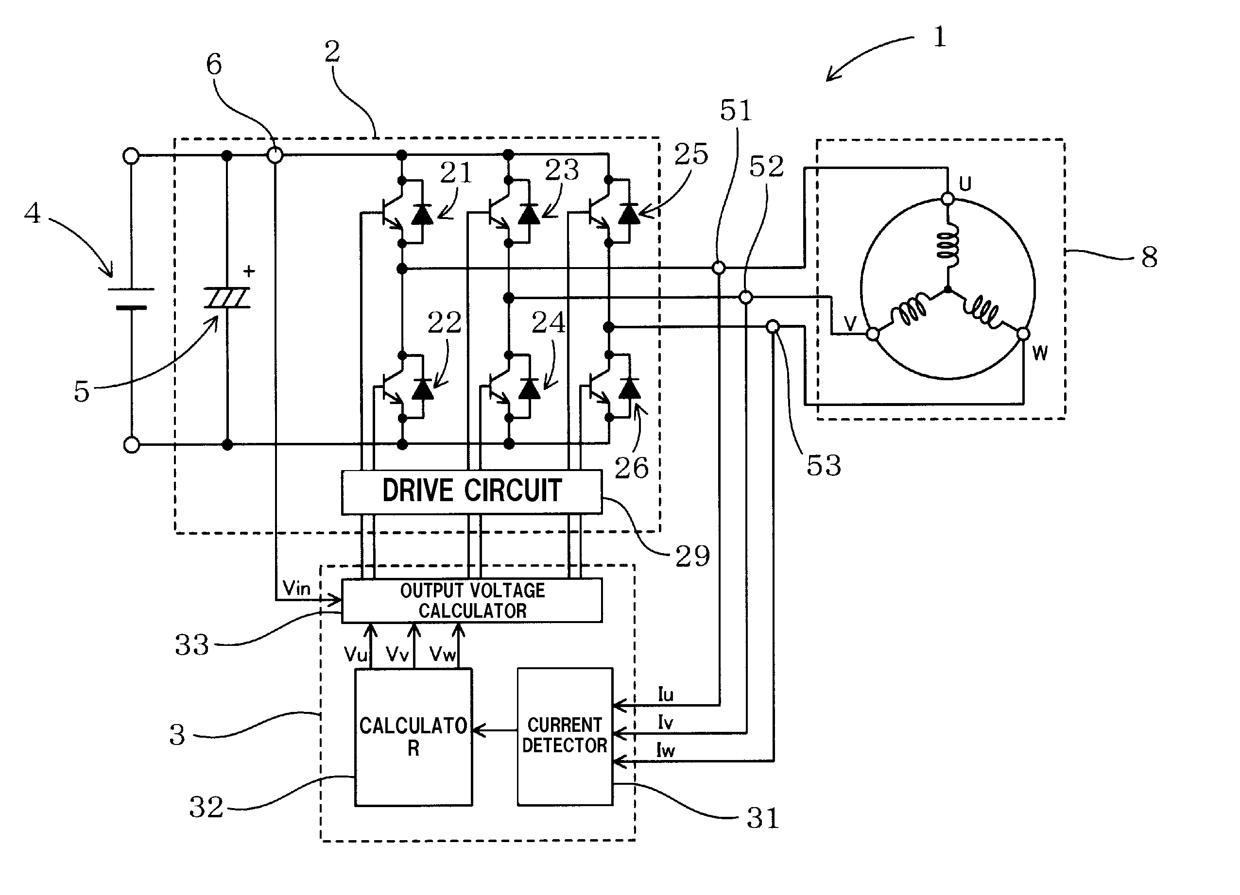
  • Method for detecting deterioration of permanent magnet in electric motor and system for the method
  • Method for detecting deterioration of permanent magnet in electric motor and system for the method
  • Method for detecting deterioration of permanent magnet in electric motor and system for the method

Examples


Embodiment Construction

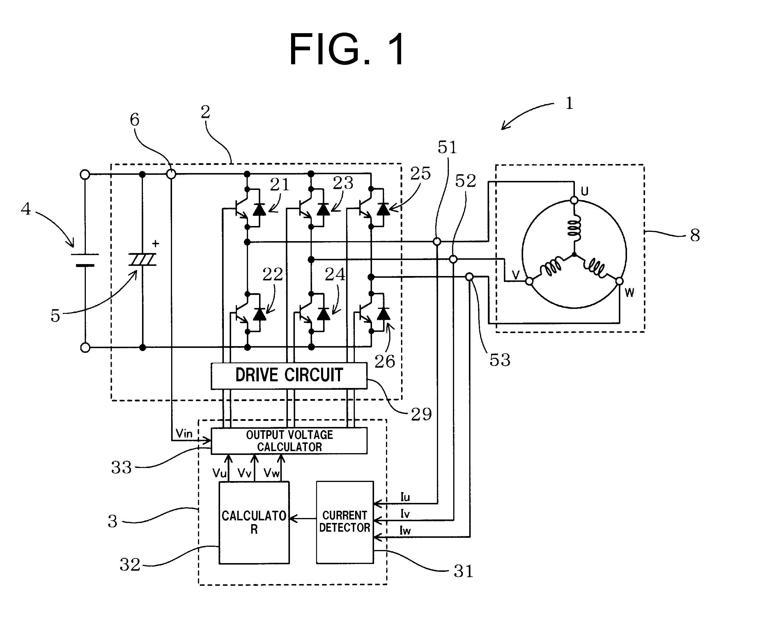
[0023]The following will describe a method for detecting deterioration of a permanent magnet of an electric motor and a system for the method according to a first preferred embodiment of the present invention with reference to FIGS. 1 through 7.

[0024]Referring to FIG. 1, a system for detecting deterioration of a permanent magnet in an electric motor is generally designated by numeral 1 and the electric motor by numeral 8, respectively. Referring to FIG. 3, the electric motor 8 has a stator core 81 around which three-phase coils serving as a multi-phase coils are wound and a rotor 82 incorporating therein a permanent magnet 83. The system 1 is used for detecting any deterioration of the permanent magnet 83 of the electric motor 8. The electric motor 8 is incorporated in a motor compressor for a vehicle air conditioner, and the system 1 is mounted in a vehicle together with the motor compressor for a vehicle air conditioner (not shown). For the sake of illustration, the electric motor...


PUM


Abstract

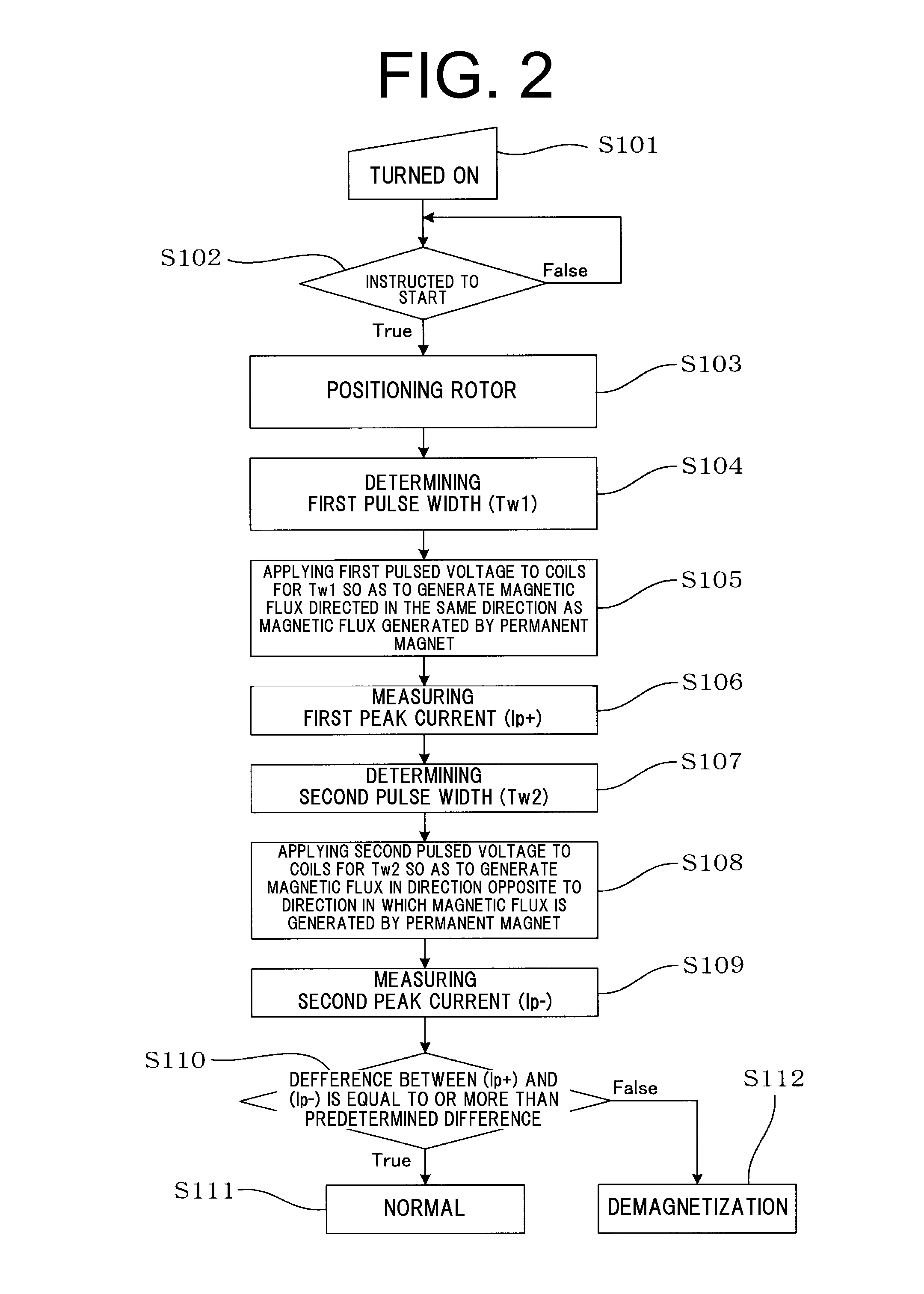
A method for detecting deterioration of a permanent magnet in an electric motor is characterized by peak current measuring steps and a determination step. In the first peak current measuring step, when the electric motor is started, a first pulsed voltage is applied to the multi-phase coils so as to generate magnetic flux directed in the same direction as generated by the permanent magnet and a first peak current is measured. In a second peak current measuring step, a second pulsed voltage is applied to the multi-phase coils so as to generate magnetic flux directed in the direction opposite to the direction in which magnetic flux is generated by the permanent magnet and a second peak current is measured. In a determination step, it is determined whether or not the permanent magnet is deteriorated based on the difference of the absolute value between the first and the second peak currents.

Description

BACKGROUND OF THE INVENTION[0001]The present invention relates to a method for detecting deterioration of a permanent magnet incorporated in an electric motor in a motor compressor used for a vehicle air conditioner and also to a system for the method.[0002]A motor compressor incorporating therein an electric motor has been used in a refrigeration cycle for a vehicle air conditioner. As a motor for such a use, a compact and high-performance electric motor having a rotor including a permanent magnet (Interior Permanent Magnet (IPM) Motor) is useful. Such a motor and a device for driving such motor are disclosed in Japanese Patent Application Publication No. 2004-7924 and Japanese Patent Application Publication No. 2006-166574.[0003]In such type of electric motor, the characteristics of the permanent magnet in the rotor of the electric motor influences the overall characteristics of the electric motor. Thus, it is important to prevent the deterioration of any permanent magnet, and als...

Claims


Application Information

Patent Timeline
Patent Type & Authority Applications(United States)
IPC IPC(8): H02P6/08H02P6/06H02P6/16
CPCG01R33/007G01R33/1207G01R33/10
Inventor FUKASAKU, HIROSHINAJIMA, KAZUKI
Owner TOYOTA IND CORP
Why Eureka
Eureka Blog
Learn More