Liquid crystal display panel
- Summary
- Abstract
- Description
- Claims
- Application Information
AI Technical Summary
Benefits of technology
Problems solved by technology
Method used
Image

Examples
first embodiment
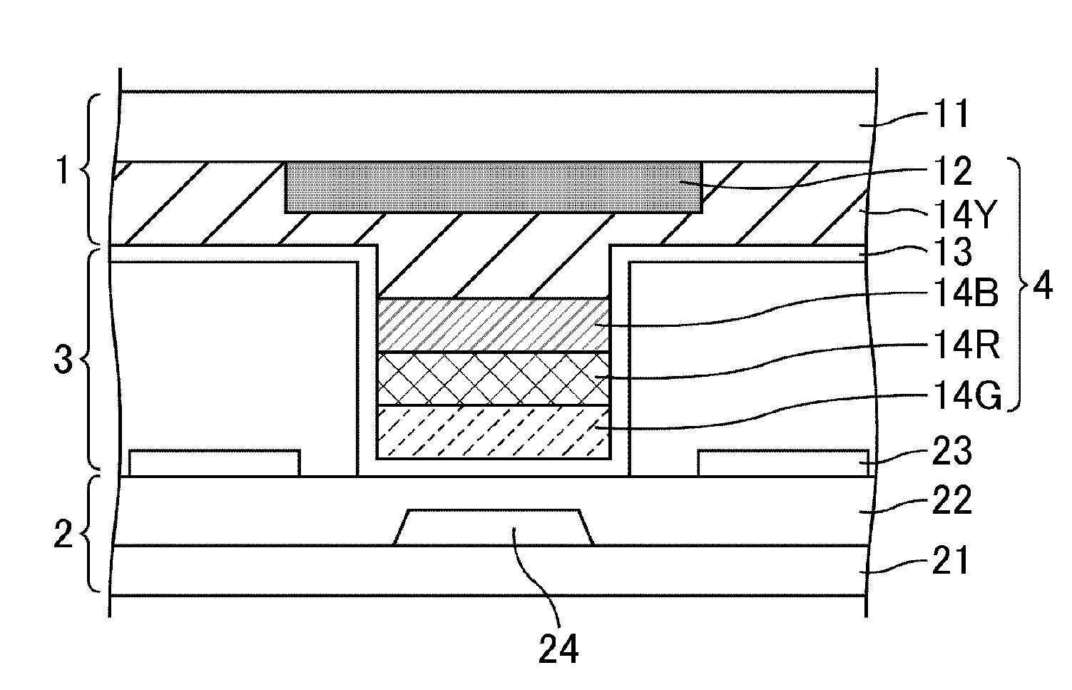
[0046]FIG. 1 is a cross-sectional view of a liquid crystal display panel of the first embodiment which schematically illustrates an area where a laminate spacer is formed. As shown in FIG. 1, the liquid crystal display panel of the first embodiment includes a liquid crystal layer 3 sandwiched between an array substrate 2 and a color filter substrate 1, and a laminate spacer 4 ensures a distance (cell gap) between the array substrate 2 and the color filter substrate 1. The laminate spacer 4 is formed on the color filter substrate 1 and their top layers are in contact with the array substrate 1.
[0047]Both the array substrate 2 and the color filter substrate 1 are mainly composed of insulating substrates 11 and 21, respectively, and various components are formed on the insulating substrate 11 and 21.
[0048]The laminate spacer 4 includes a black matrix (light blocking layer) 12; a yellow color filter (transparent colored layer) 14Y; a blue color filter (transparent colored layer) 14B; a ...
second embodiment
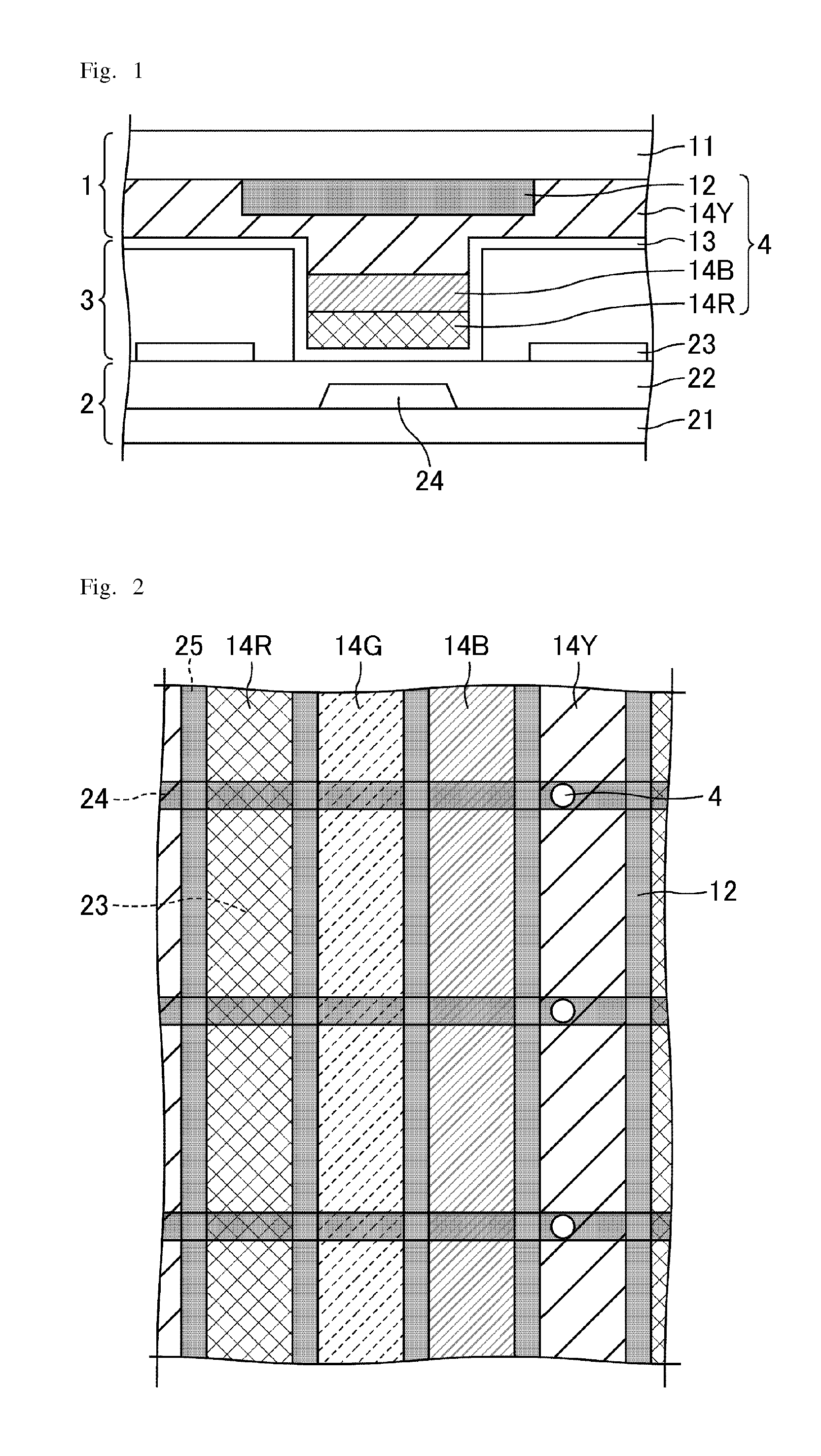
[0069]The liquid crystal display panel of the second embodiment has the same structure as the liquid crystal display panel of the first embodiment, except that dots of the yellow color filter 14Y are formed in accordance with the pixels unlike the stripe pattern.
[0070]FIG. 11 is a schematic plan view of the liquid crystal display panel of the second embodiment. As shown in FIG. 11, the yellow color filter 14Y of the second embodiment is divided in accordance with the pixels by the black matrix 12 that overlaps the gate lines 24 and the source lines 25. As a whole, a plurality of yellow filters 14Y are arranged in a stripe pattern along the column direction.
[0071]In the second embodiment, the laminate spacer 4 is surrounded by the yellow color filters 14Y and overlaps the gate lines 24. Since the laminate spacer 4 is surrounded by the yellow pixels, this structure can avoid a large impact on the display quality even if a short circuit arises between the common electrode 13 and the pi...
third embodiment
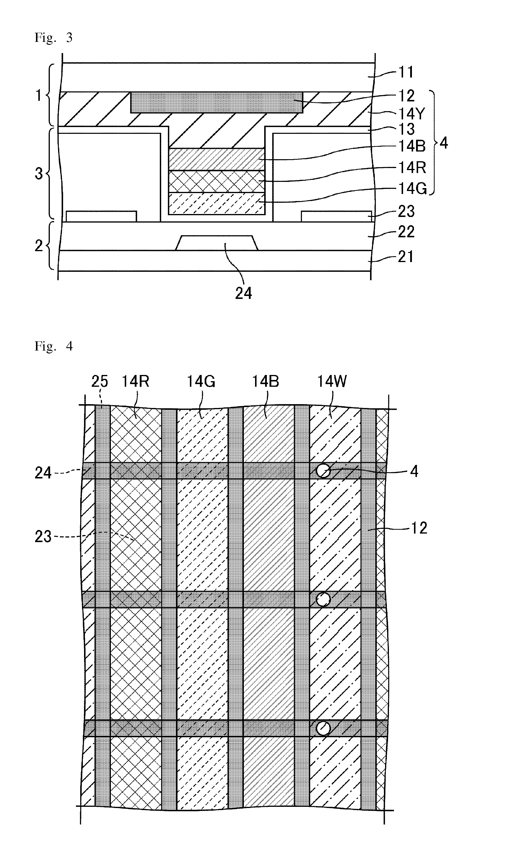
[0075]The liquid crystal display panel of the third embodiment has the same structure as the liquid crystal display panel of the first embodiment, except that the top layer of the laminate spacer is not the common electrode. FIG. 15 is across-sectional view of the liquid crystal display panel of the third embodiment which schematically illustrates an area where the laminate spacer is formed. In the third embodiment, as shown in FIG. 15, the black matrix 12 constitutes the top layer of the laminate spacer 4, the common electrode 13 is sandwiched between the red color filter 14R and the black matrix 12. This structure can be formed by changing the order of the production processes of the components of the laminate spacer 4 (the order of layers).
[0076]The laminate spacer 4 according to the third embodiment is surrounded by the yellow color filter 14Y that is formed in a stripe pattern, and overlap the gate lines 24. Since the laminate spacer 4 is surrounded by the yellow pixels, this s...
PUM
 Abstract
Description
Claims
Application Information
 - R&D
- Intellectual Property
- Life Sciences
- Materials
- Tech Scout
- Unparalleled Data Quality
- Higher Quality Content
- 60% Fewer Hallucinations
Browse by: Latest US Patents, China's latest patents, Technical Efficacy Thesaurus, Application Domain, Technology Topic, Popular Technical Reports.
© 2025 PatSnap. All rights reserved.Legal|Privacy policy|Modern Slavery Act Transparency Statement|Sitemap|About US| Contact US: help@patsnap.com