Method and system for self-adapting dynamic power reduction mechanism for physical layer devices in packet data networks

a dynamic power reduction and physical layer technology, applied in the field of network work, can solve the problems that the delivery of such time-sensitive information creates a serious burden on networks and network designers

Inactive Publication Date: 2012-07-26
AVAGO TECH WIRELESS IP SINGAPORE PTE
View PDF2 Cites 28 Cited by
  • Summary
  • Abstract
  • Description
  • Claims
  • Application Information

AI Technical Summary

Benefits of technology

[0019]FIG. 4 is a flow chart that illustrates exemplary transmit (Tx) based power control policy for use during self-adapting dynamic power reduction servicing in a physical layer (PHY), in accordance with an embodiment of the invention.
[

Problems solved by technology

However, delivery of such time-sensitive information cre

Method used


Image

  • Method and system for self-adapting dynamic power reduction mechanism for physical layer devices in packet data networks
  • Method and system for self-adapting dynamic power reduction mechanism for physical layer devices in packet data networks
  • Method and system for self-adapting dynamic power reduction mechanism for physical layer devices in packet data networks

Examples


Embodiment Construction

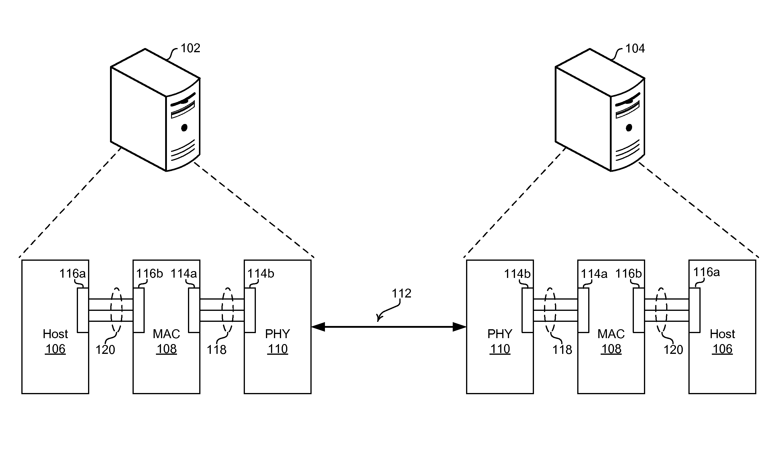
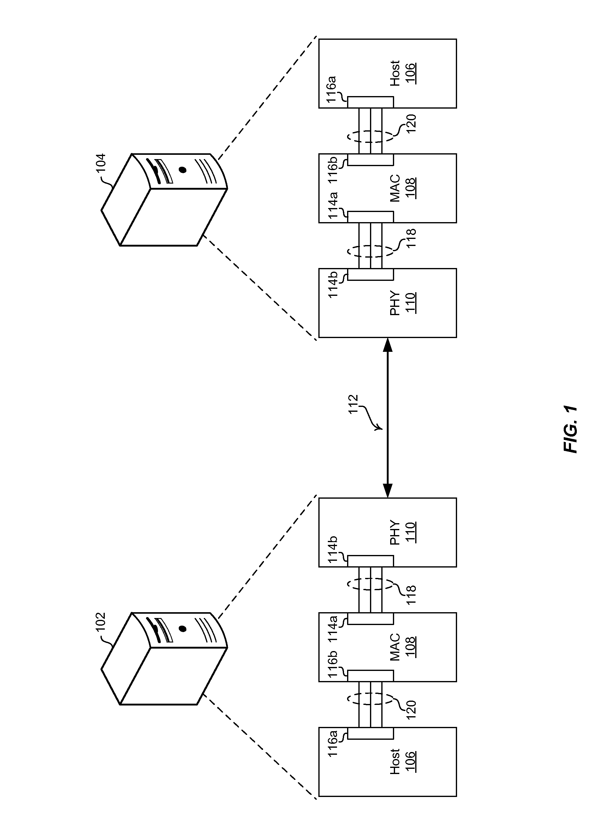
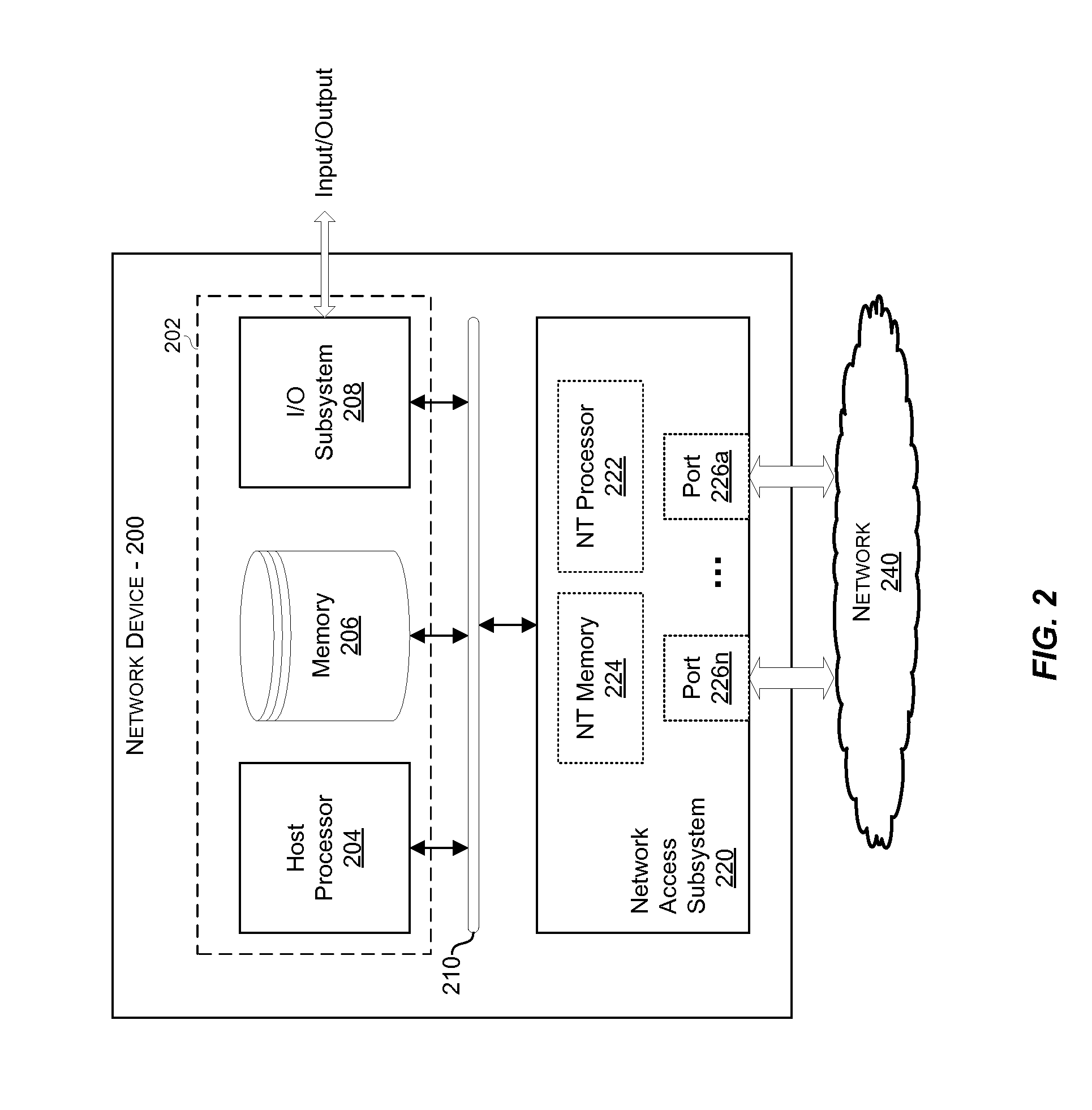
[0021]Certain embodiments of the invention may be found in a method and system for self-adapting dynamic power reduction mechanism for physical layer devices in packet data networks. In various embodiments of the invention, a physical layer (PHY) in a network device may provide self-adapting power reduction based on monitoring of activity associated with an interface between the PHY and remaining components of the network device. The power management operations of the PHY may then be configured and / or adjusted based on that monitoring. The PHY may comprise an Ethernet PHY, which may be operable to support energy efficient Ethernet (EEE) features. The monitored interface may comprise a Media Independent Interface (MII) based interface. In instances where the monitored activity comprises outbound traffic, outbound data, which is received for transmission, via the interface may be buffered when at least one subcomponent of the PHY that is operable to support transmission of the outboun...


PUM


Abstract

A physical layer (PHY) in a network device may provide self-adapting power reduction based on monitoring of activity associated with an interface between the PHY and remaining components of the network device. The power management operations of the PHY may then be configured and/or adjusted based on that monitoring. The PHY may comprise an Ethernet PHY, which may support energy efficient Ethernet (EEE) features. The monitored interface may comprise a Media Independent Interface (MII) based interface. In instances where the monitored activity comprises outbound traffic, outbound data received via the interface may be buffered when at least one subcomponent of the PHY that is operable to support transmission of the outbound traffic is unavailable due to the power management operations. The buffering may be configured to last to allow sufficient time to reactivate the at least one subcomponent.

Description

CLAIM OF PRIORITY[0001]This patent application makes reference to, claims priority to and claims benefit from U.S. Provisional Application Ser. No. 61 / 434,801 (Attorney Docket No. 24116US01) which was filed on Jan. 20, 2011.[0002]The above stated application is hereby incorporated herein by reference in its entirety.CROSS-REFERENCE TO RELATED APPLICATIONS / INCORPORATION BY REFERENCE[0003]This application makes reference to:[0004]U.S. patent application Ser. No. 12 / 470,970 filed on May 22, 2009;[0005]U.S. patent application Ser. No. 12 / 480,658 filed on Jun. 8, 2009; and[0006]U.S. patent application Ser. No. 12 / 490,209 filed on Jun. 23, 2009.[0007]Each of the above stated applications is hereby incorporated herein by reference in its entirety.FEDERALLY SPONSORED RESEARCH OR DEVELOPMENT[0008][Not Applicable].MICROFICHE / COPYRIGHT REFERENCE [0009][Not Applicable].FIELD OF THE INVENTION[0010]Certain embodiments of the invention relate to networking. More specifically, certain embodiments o...

Claims


Application Information

Patent Timeline
IPC IPC(8): H04L12/26
CPCH04L12/10H04L41/0816H04L43/08Y02B60/32H04L41/0833Y02B60/35Y02B60/34H04L12/12Y02D30/50H04L69/323H04L69/324H04L12/28G06F1/32
Inventor TAZEBAY, MEHMETPOWELL, SCOTT
Owner AVAGO TECH WIRELESS IP SINGAPORE PTE
Why Eureka
Try Eureka