Refrigerant vapor compression system operation

a refrigeration vapor compression and vapor compression technology, applied in the field of vapor compression systems, can solve the problems of refrigerant leaking from the system, potential for refrigerant to be trapped in isolated pockets of the refrigerant circuit, and the system is subject to cycling between the operating mode and the standstill mode, so as to relieve the pressure of refrigeran

Active Publication Date: 2012-08-02
CARRIER CORP
View PDF13 Cites 69 Cited by
  • Summary
  • Abstract
  • Description
  • Claims
  • Application Information

AI Technical Summary

Benefits of technology

[0012]A method is provided for protecting a refrigerant vapor compression system during a standstill period following shutdown of the refrigerant vapor compression system. The refrigerant vapor compression system has a primary refrigerant circuit having a high-pressure side downstream with respect to refrigerant flow of a compression device and upstream with respect to refrigerant flow of a primary expansion device and a low-pressure...

Problems solved by technology

Additionally, transport refrigerant vapor compression systems are subject to cycling between an operating mode and standstill mode, i.e. an idle state.
With the flow control devices fully closed, the potential exists for refrigerant to be trapped in isolated pockets of ...

Method used


Image

  • Refrigerant vapor compression system operation
  • Refrigerant vapor compression system operation
  • Refrigerant vapor compression system operation

Examples


Embodiment Construction

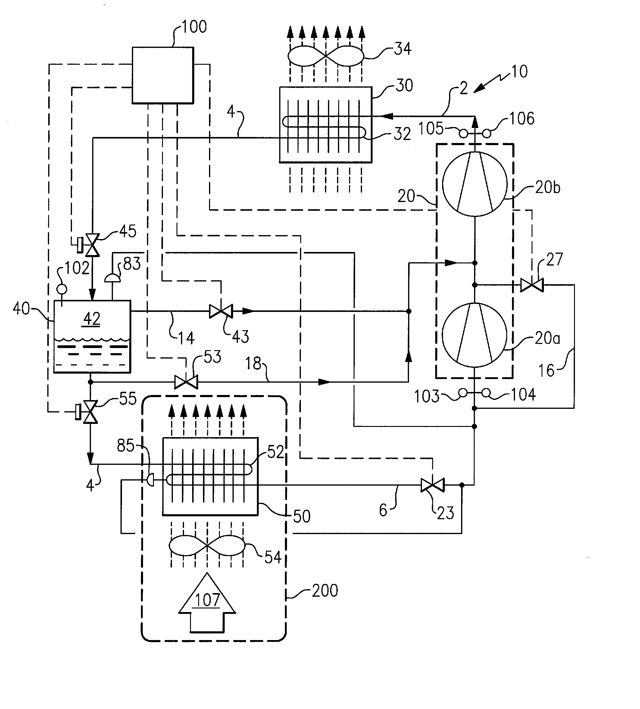
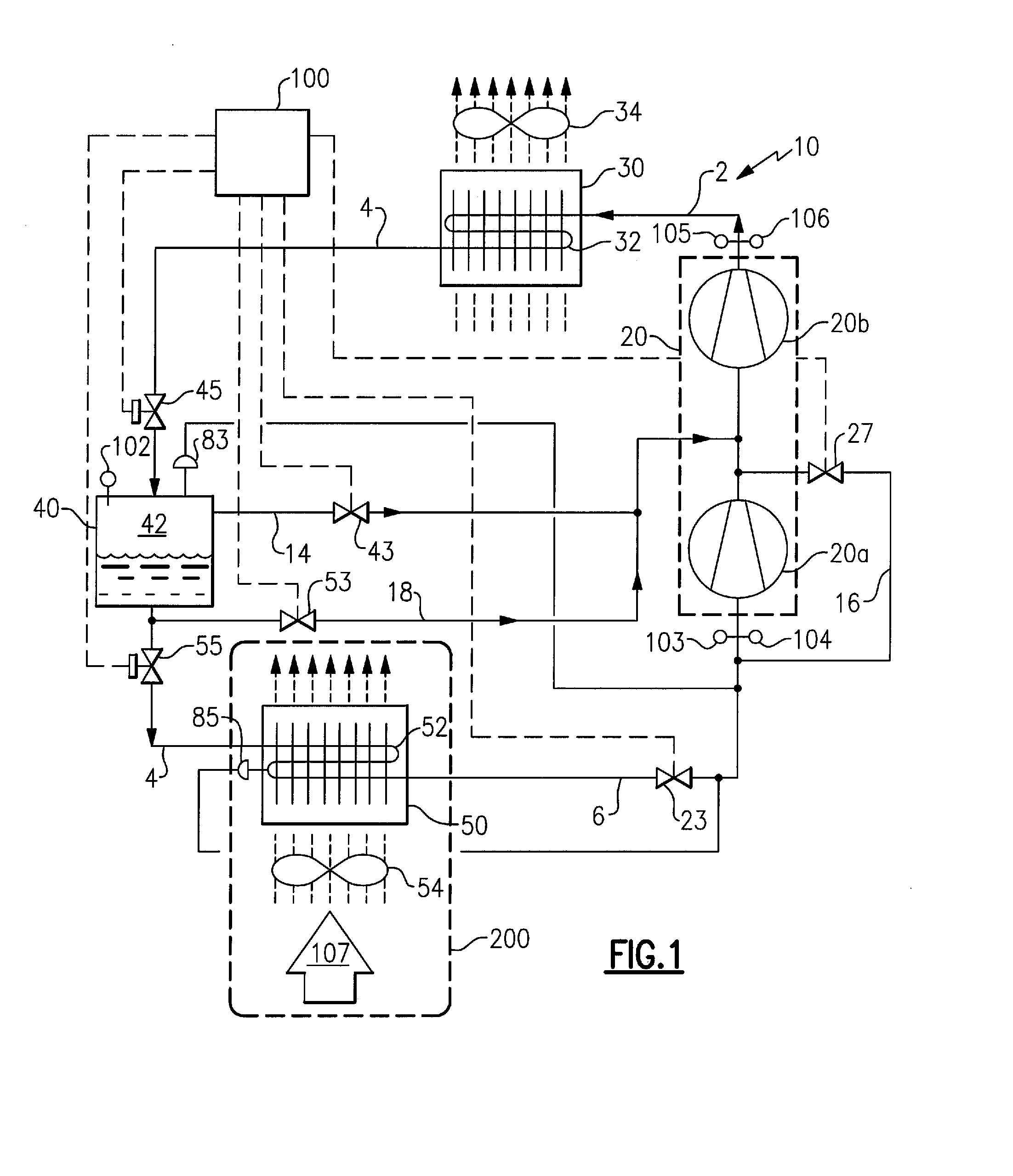
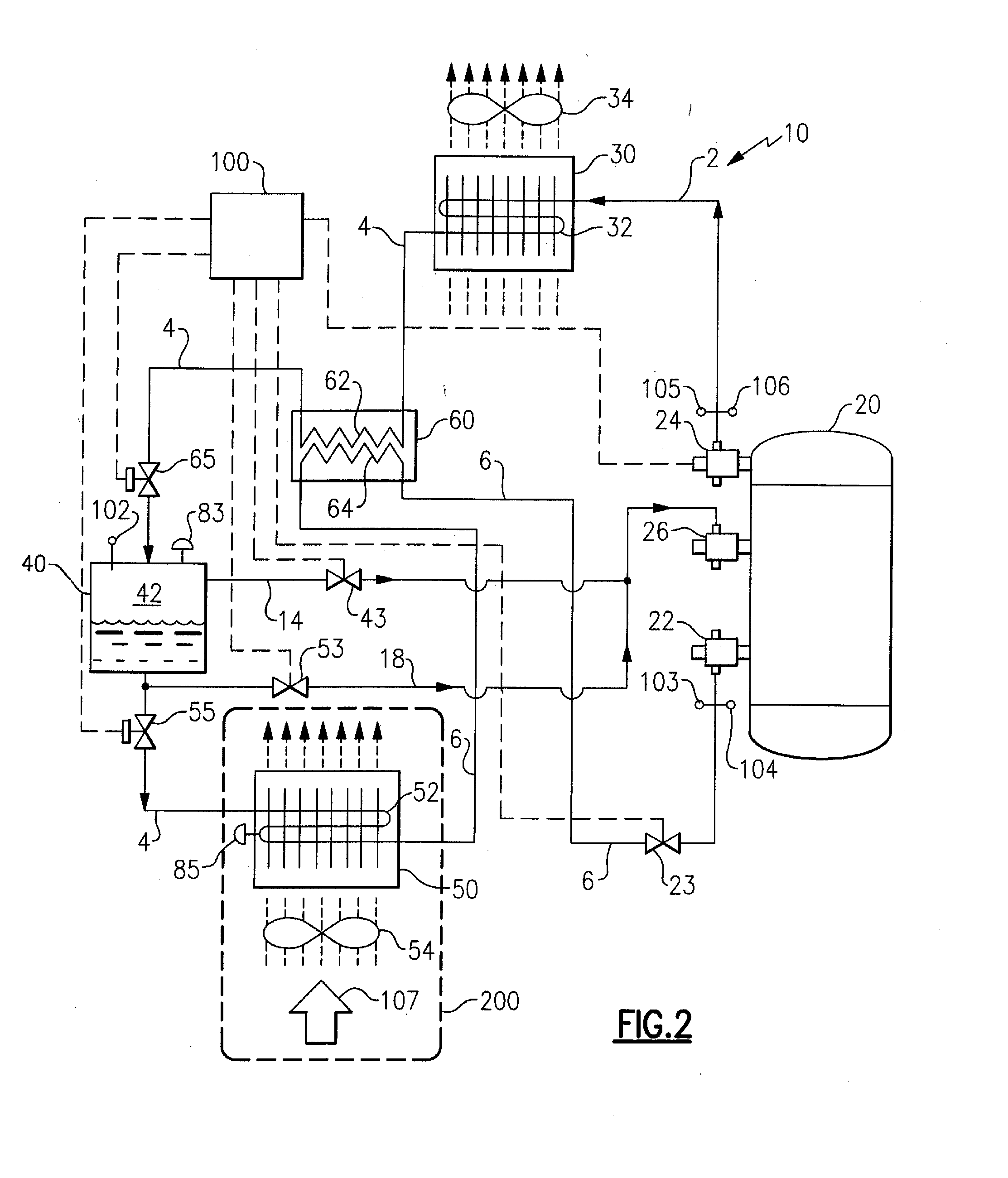
[0027]Referring initially to FIGS. 1 and 2 of the drawing, there are depicted exemplary embodiments of a refrigerant vapor compression system 10 designed for operation in a transcritical cycle with a low critical point refrigerant, such as for example, but not limited to, carbon dioxide and refrigerant mixtures containing carbon dioxide. However, it is to be understood that the refrigerant vapor compression system 10 may also be operated in a subcritical cycle with a higher critical point refrigerant such as conventional hydrochlorofluorocarbon and hydrofluorocarbon refrigerants.

[0028]The refrigerant vapor compression system 10 is particularly suitable for use in a transport refrigeration system for refrigerating the air or other gaseous atmosphere within the temperature controlled cargo space 200 of a truck, trailer, container or the like for transporting perishable / frozen goods. The refrigerant vapor compression system 10 is also suitable for use in conditioning air to be supplied...


PUM


Abstract

A method is provided for protecting a refrigerant vapor compression system during a standstill period following shutdown of the refrigerant vapor compression system. A method is provided for detecting a low refrigerant charge level in a refrigerant vapor compression system operating in a transcritical mode. A refrigerant vapor compression system is provided that includes a controller operative to perform a refrigerant charge detection method.

Description

CROSS-REFERENCE TO RELATED APPLICATION[0001]Reference is made to and this application claims priority from and the benefit of U.S. Provisional Application Ser. No. 61 / 254,277, filed Oct. 23, 2009, and entitled REFRIGERANT VAPOR COMPRESSION SYSTEM OPERATION, which application is incorporated herein in its entirety by reference.FIELD OF THE INVENTION[0002]This invention relates generally to vapor compression systems and, more particularly, to the operation of refrigeration vapor compression systems.BACKGROUND OF THE INVENTION[0003]Conventional vapor compression systems typically include a compressor, a heat rejection heat exchanger, a heat absorption heat exchanger, and expansion device, commonly an expansion valve, disposed upstream with respect to working fluid flow, of the heat absorption heat exchanger and downstream of the heat rejection heat exchanger. These basic system components are interconnected by working fluid lines in a closed circuit, arranged in accord with known vapor...

Claims


Application Information

Patent Timeline
IPC IPC(8): F25B49/02F25B41/04F25B1/00
CPCB60H1/3232F25B1/10F25B9/008F25B41/043F25B45/00F25B49/005F25B2600/2525F25B2400/13F25B2400/23F25B2500/07F25B2600/0261F25B2600/2509F25B2309/061B60H1/3228F25B31/008F25B41/22
Inventor HUFF, HANS-JOACHIMLIU, LUCY YIDURAISAMY, SURESHASPROVSKI, ZVONKOROGERS, MARK S.LEE, KEONWOO
Owner CARRIER CORP
Why Eureka
Try Eureka