
Co2 refrigeration system

a refrigeration system and co2 technology, applied in the field of refrigeration systems, can solve the problems of high flammability of refrigerants and represent a risk to local safety, and achieve the effect of relieving the pressure of co2 refrigerants

Inactive Publication Date: 2012-03-08
DUBE SERGE
View PDF11 Cites 26 Cited by
  • Summary
  • Abstract
  • Description
  • Claims
  • Application Information

AI Technical Summary

Benefits of technology

[0024]In accordance with a second embodiment of the present application, there is provided a method for relieving CO2 refrigerant pressure from evaporators during a defrost cycle, comprising: providing a pressure-relief valve for each evaporator line, the pressure relief-valve opening at a pressure threshold; feeding CO2 refrigerant to at least one evaporator in the evaporator line to defrost the evaporator; exhausting the evaporator from the CO2 refrigerant with the pressure-relief valve when the CO2 refrigerant pressure is above the pressure threshold; and directing the exhausted CO2 refrigerant to an accumulator in a refrigeration cycle.

Problems solved by technology

Although ammonia and hydrocarbons have negligible ozone-depletion potential and global-warming potential as does CO2, these refrigerants are highly flammable and therefore represent a risk to local safety.

Method used


Image

  • Co2 refrigeration system
  • Co2 refrigeration system
  • Co2 refrigeration system

Examples


Embodiment Construction

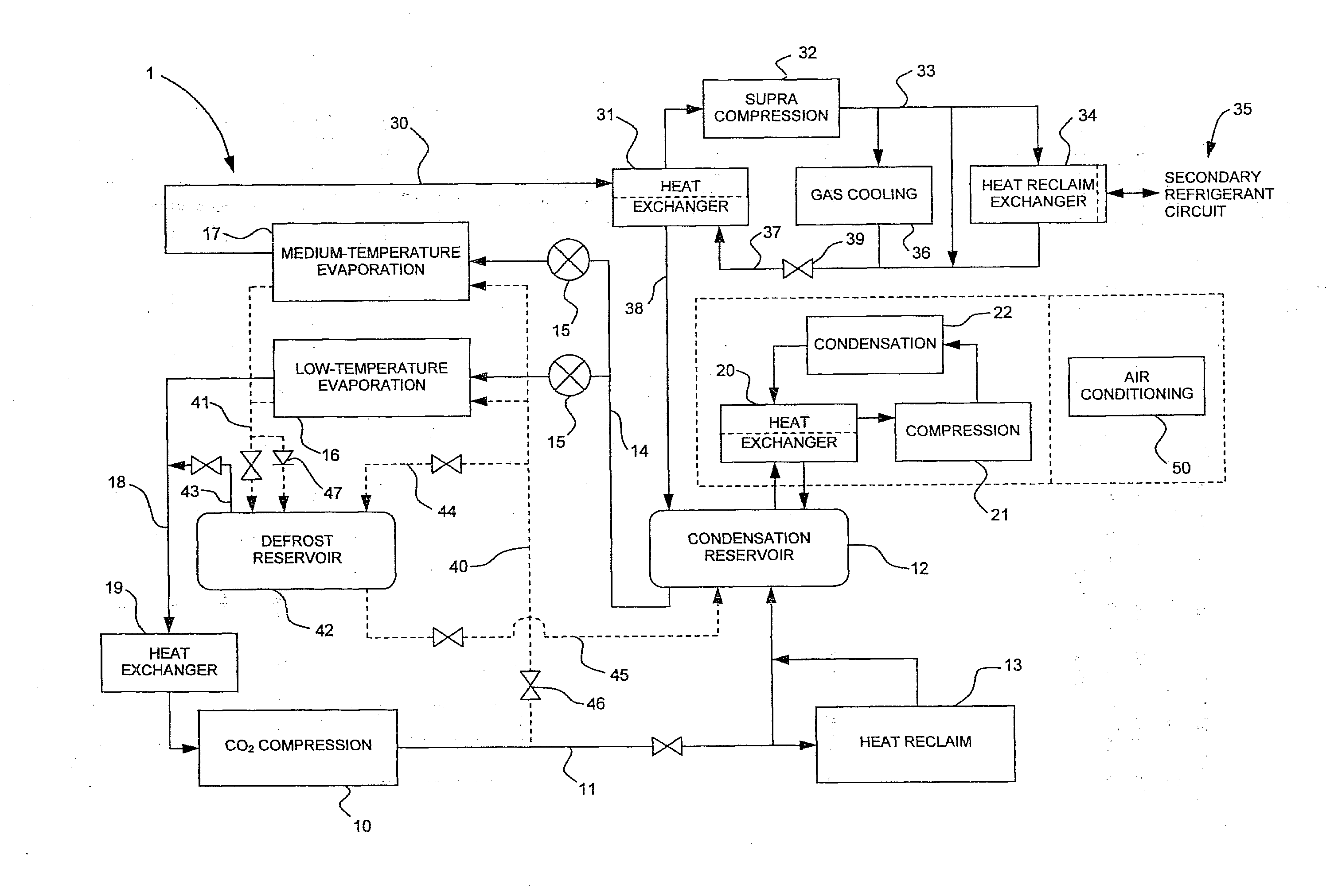
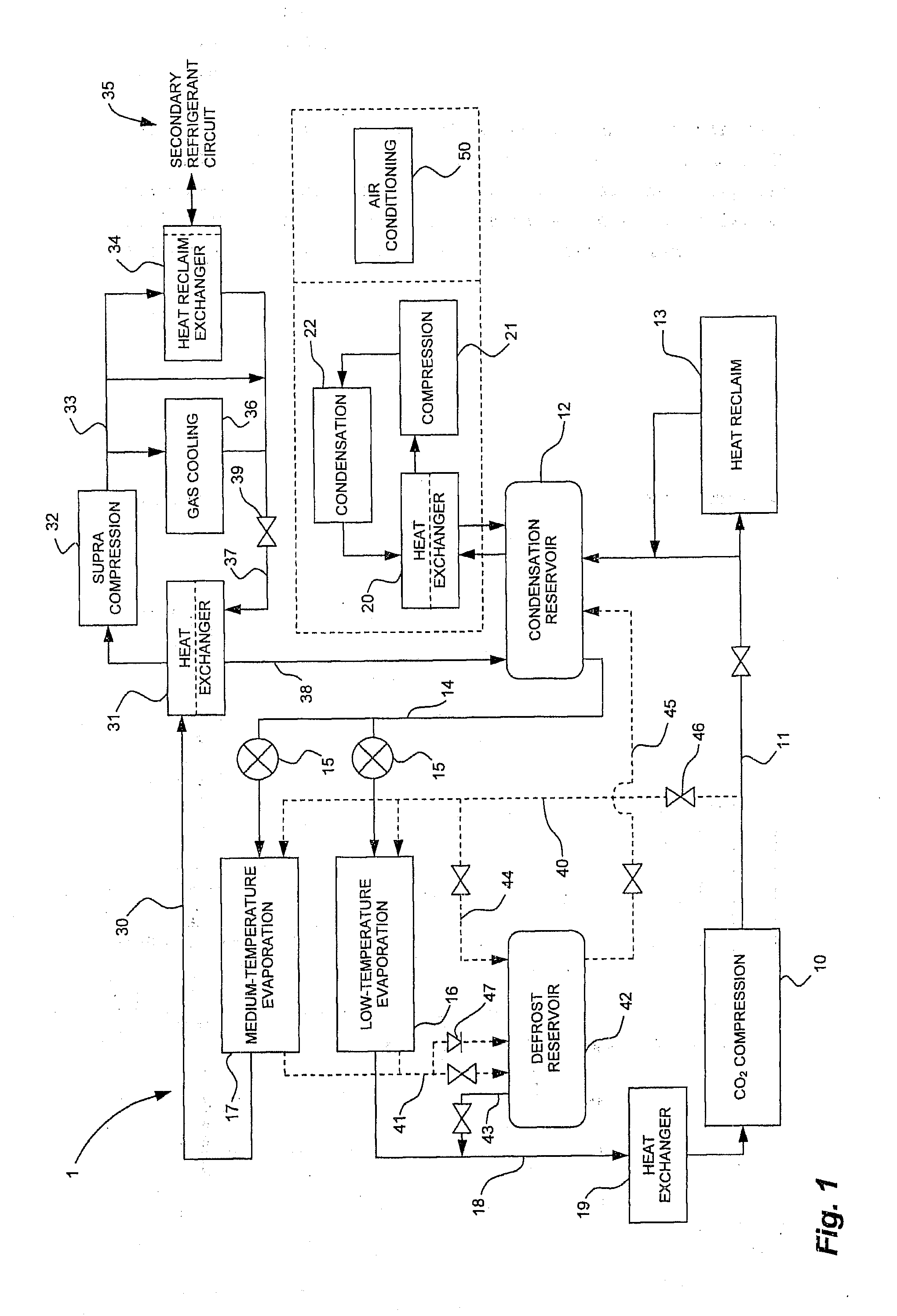
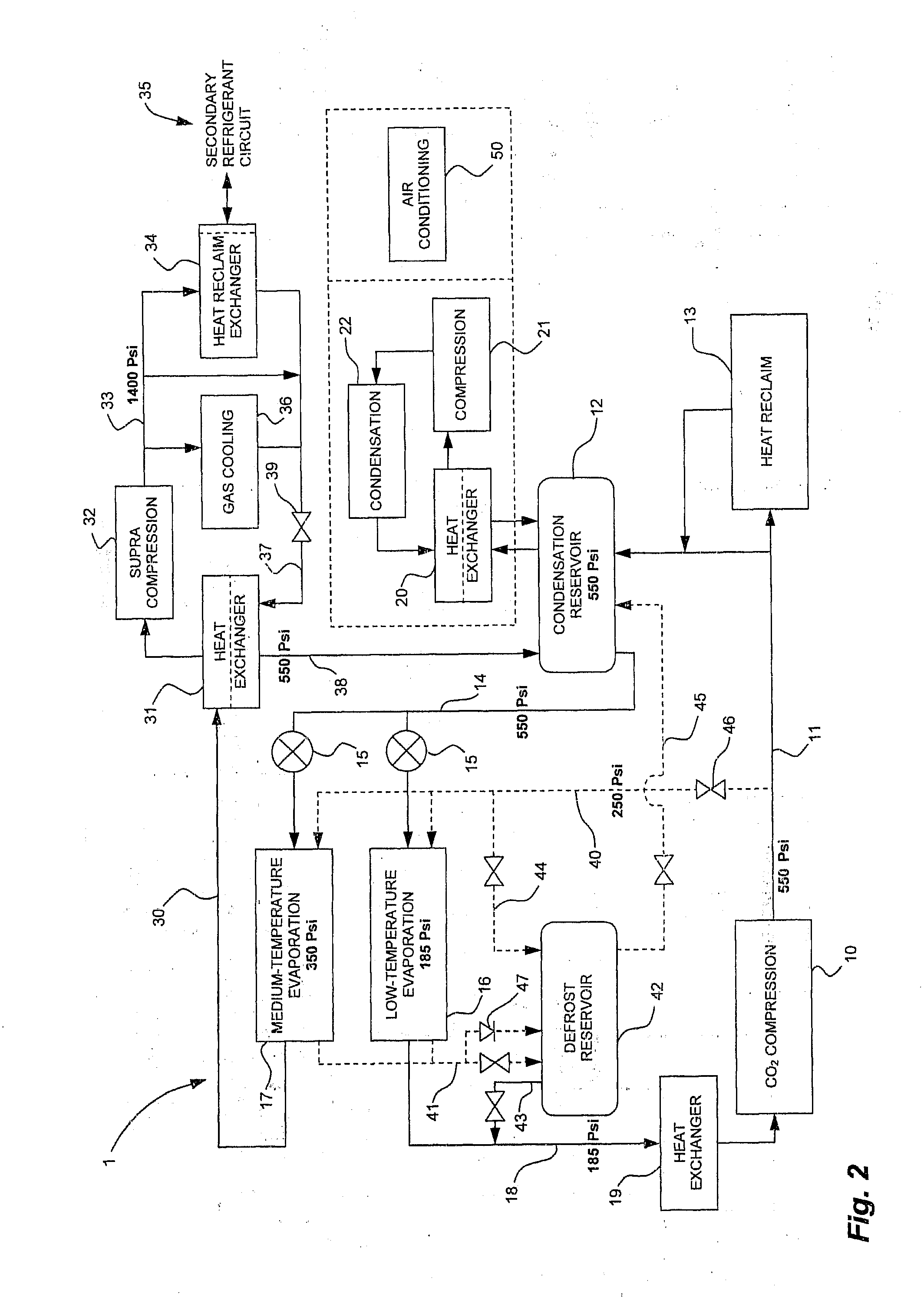
[0041]Referring to FIG. 1, a CO2 refrigeration system in accordance with an embodiment is illustrated at 1. The CO2 refrigeration system 1 has a CO2 refrigeration circuit comprising a CO2 compression stage 10. CO2 refrigerant is compressed in the compression stage 10, and is subsequently directed via line 11 to a condensation reservoir 12, or to a heat-reclaim stage 13.

[0042]The condensation reservoir 12 accumulates CO2 refrigerant in a liquid and gaseous state, and is in a heat-exchange relation with a condensation circuit that absorbs heat from the CO2 refrigerant. The condensation circuit is described in further detail hereinafter. Moreover, a transcritical circuit and a defrost circuit may supply CO2 refrigerant to the condensation reservoir 12, as is described in further detail hereinafter.

[0043]The heat-reclaim stage 13 is provided to absorb heat from the CO2 refrigerant exiting from the compression stage 10. The heat-reclaim stage 13 may take various forms, such as that of a ...


PUM


Abstract

A CO2 refrigeration system comprises a refrigeration circuit in which circulates CO2 refrigerant between a compression stage in which the CO2 refrigerant is compressed. A condensation stage is provided in which the CO2 refrigerant releases heat and is accumulated in a condensation reservoir. An evaporation stage is provided in which the CO2 refrigerant is expanded to a gaseous state to absorb heat from a fluid for refrigeration, with at least a portion of CO2 refrigerant exiting the evaporation stage being directed to a supra-compression circuit comprising a supra-compression stage in which the portion of CO2 refrigerant is compressed. A heat exchanger is provided by which the compressed CO2 refrigerant is in a heat-exchange relation with a secondary-refrigerant circuit, such that the compressed CO2 refrigerant releases heat to a secondary refrigerant used for heating purposes. Pressure-regulating means control a pressure of the compressed CO2 refrigerant being returned to the condensation stage.

Description

CROSS-REFERENCE TO RELATED APPLICATIONS[0001]This patent application claims priority on U.S. Patent Application No. 61 / 107,689, filed on Oct. 23, 2008, No. 61 / 166,884, filed on Apr. 6, 2009, and No. 61 / 184,021, filed on Jun. 4, 2009.FIELD OF THE APPLICATION[0002]The present application relates to refrigeration systems, and more particularly to refrigeration systems using CO2 refrigerant.BACKGROUND OF THE ART[0003]With the growing concern for global warming, the use of chlorofluorocarbons (CFCs) and hydrochloro-fluorocarbons (HCFCs) as refrigerant has been identified as having a negative impact on the environment. These chemicals have non-negligible ozone-depletion potential and / or global-warming potential.[0004]As alternatives to CFCs and HCFCs, ammonia, hydrocarbons and CO2 are used as refrigerants. Although ammonia and hydrocarbons have negligible ozone-depletion potential and global-warming potential as does CO2, these refrigerants are highly flammable and therefore represent a r...

Claims


Application Information

Patent Timeline
Patent Type & Authority Applications(United States)
IPC IPC(8): F25D21/06F25B39/02F25B41/00F25B39/04F25B41/04
CPCF24F3/1417F24F2003/144F25B2309/06F25B9/008F25B29/003F25B5/02F25C3/02F25B31/00F25B31/004F25B2309/061
Inventor DUBE, SERGE
Owner DUBE SERGE
Learn More