Reduced Energy Training Cartridge for Straight Blow Back Operated Firearms

a training cartridge and straight blowback technology, applied in the field of ammunition, can solve the problems of reducing energy cartridge casings, relatively expensive cartridge brass for reducing energy cartridge casing applications, and polymerization is generally not a good choice, so as to achieve the effect of reducing energy

Active Publication Date: 2012-08-02
GENERAL DYNAMICS ORDNANCE & TACTICAL SYST CANADA VALLEYFIELD INC
View PDF2 Cites 14 Cited by
  • Summary
  • Abstract
  • Description
  • Claims
  • Application Information

AI Technical Summary

Benefits of technology

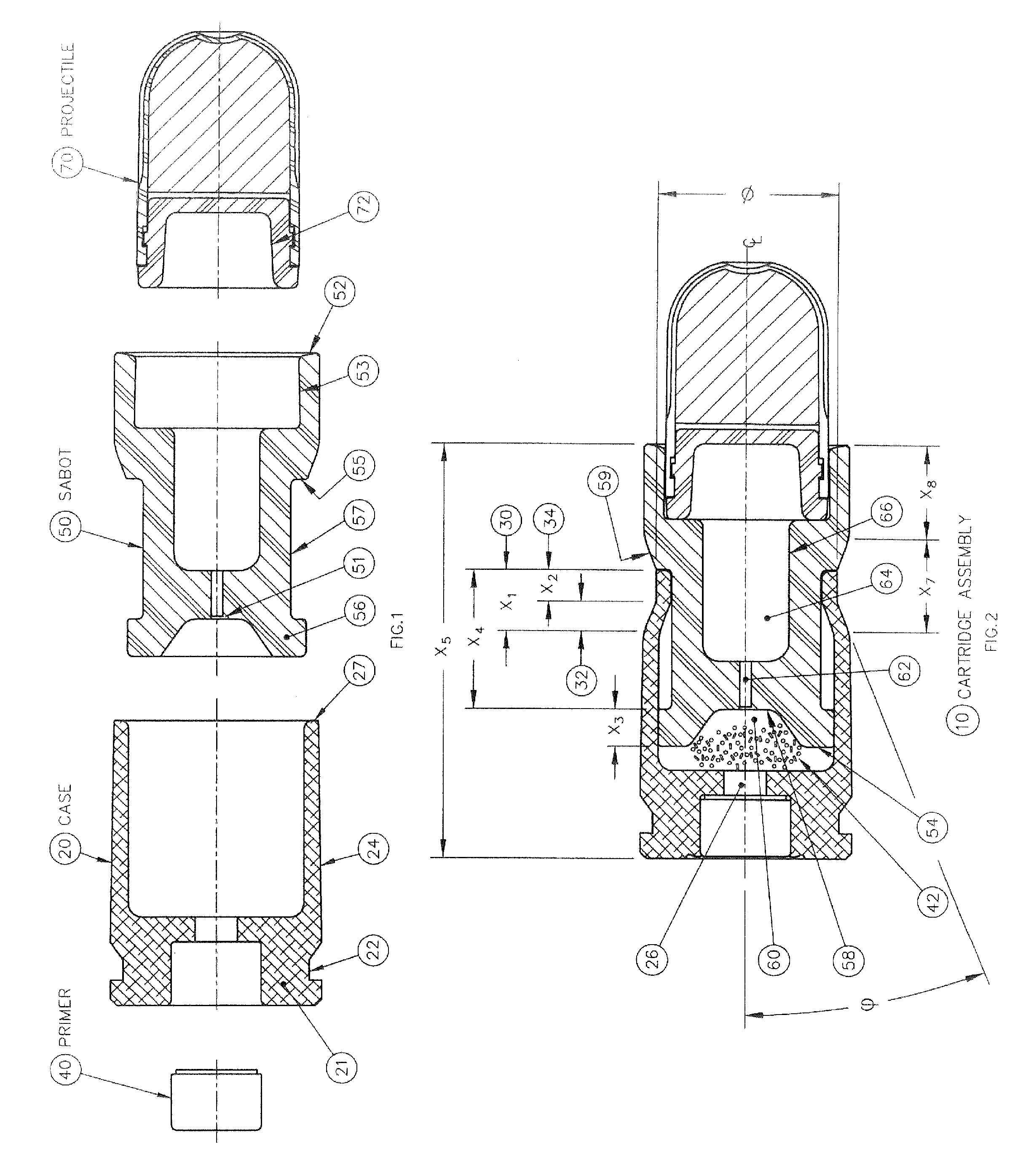
[0008]The present invention discloses a reduced energy training cartridges for use in straight blowback operated firearms. The subject design can be applied to a variety of calibers, including 9 mm, 5.56 mm, etc., as well as various external ballistics or blank cartridge applications relating to the same. The cartridge comprising a cartridge case being defined by a rear portion with an external groove, a front portion having a velocity reduction structure and a wall with an outer surface and an inner surface, a sabot slideably engaged within the cartridge case, the sabot havi...

Problems solved by technology

First, the design of reduced energy ammunition casings in the prior art are often made of conventional cartridge brass.
However, cartridge brass is relatively expensive for reduced energy cartridge case application when compared with alternative materials such as aluminum alloys, zinc alloys, other alloys, steel or even polymers.
It is noted that the of use polymer casings is hinted at in the prior art, however polymers are not generally a good choice for the casing material for several reasons.
First, their lack of compressive strength results in an inability to retain a press-fitted primer.
Also, the relatively low tensile strength of polymer casings makes it difficult for them...

Method used


Image

  • Reduced Energy Training Cartridge for Straight Blow Back Operated Firearms
  • Reduced Energy Training Cartridge for Straight Blow Back Operated Firearms
  • Reduced Energy Training Cartridge for Straight Blow Back Operated Firearms

Examples


case 20

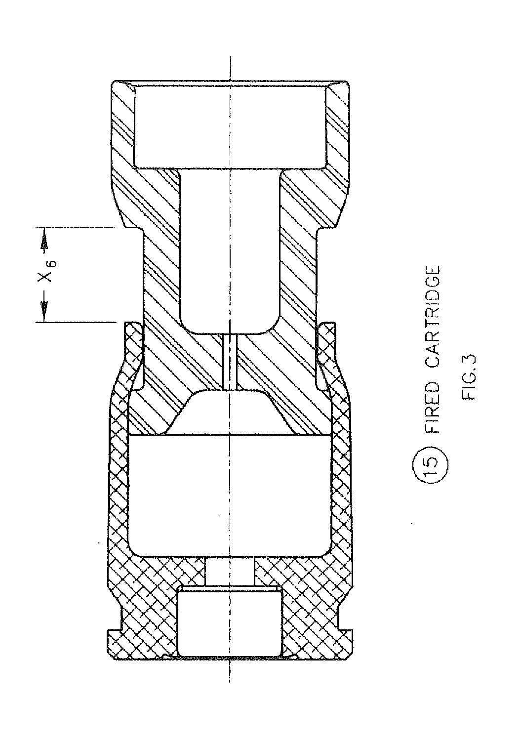
[0017]Case 20 further contains an outer wall 24, a portion of which is formed into a velocity reduction structure 30 at the front portion 27 of the case 20. Velocity reduction structure 30 is defined by a canted surface 32 and a cylindrical surface 34. In a preferred embodiment, canted surface 32 originates from outer wall 24 with a slightly curved approach, however a clearly defined angle marking the transition from outer wall 24 to canted surface 32 is also functionally acceptable. Cylindrical surface 34 is preferably a straight cylinder, i.e., is parallel to the centerline of case 20, however with appropriate tooling, cylindrical surface 34 could be made tapered up to + / −10° or more and still remain effective. The external surface of velocity reduction structure 30 may have slight pinch marks generated by the assembly forming tool.

[0018]Canted surface 32 ends at a distance X1 from the front portion 27 of case 20. The degree of slant present in canted surface 32 relative to the ce...


PUM


Abstract

The present invention discloses a reduced energy training cartridge for use in a straight blowback operated firearm having a barrel with firing chamber, the cartridge comprising a cartridge case being defined by a rear portion with an external groove, a front portion having a velocity reduction structure and a wall with an outer surface and an inner surface, a sabot slideably engaged within the cartridge case, the sabot having a rear portion with an outside diameter substantially equal to the inside diameter of the inner surface of the cartridge case and which contains a gas sealing and braking structure and a primer disposed in the rear portion of the cartridge case where, upon percussion of the primer, the cartridge case rapidly slides relative to the sabot until such point when the velocity reduction structure of the cartridge case engages with the sealing and braking structure of the sabot, thereby stopping further movement of the cartridge case relative to the sabot, The present invention also contemplates using a metallic case in combination with a non-metallic or polymer sabot.

Description

FIELD OF THE INVENTION[0001]The present invention generally relates to ammunition and, more particularly to reduced energy ammunition used with straight blowback operated firearms in training exercises.BACKGROUND OF THE INVENTION[0002]Members of the military, law enforcement and other such entities greatly benefit from experiencing training exercises which are as close to real-life combat as possible in order to better hone both their marksmanship and tactical strategy. Thus, many such institutions utilize reduced energy, training products which permit the simulation of a “live fire” event without the risks associated with using conventional live ammunition. Such products can include converted or dedicated automatic or semi-automatic straight blowback operated firearms used to fire the reduced energy ammunition. Being able to employ an individual's own service-issued firearm in such training exercises brings added realism to each scenario. The projectiles fired from such modified fi...

Claims


Application Information

Patent Timeline
IPC IPC(8): F42B8/02F42B30/00
CPCF42B8/02F42B5/045
Inventor LAFORTUNE, ERIC
Owner GENERAL DYNAMICS ORDNANCE & TACTICAL SYST CANADA VALLEYFIELD INC
Why Eureka
Try Eureka