Compressed hydrogen fueling control valve

a control valve and hydrogen technology, applied in the direction of liquid handling, packaging goods type, container discharging methods, etc., can solve the problems of reducing the service life of the valv

Inactive Publication Date: 2012-08-02
GM GLOBAL TECH OPERATIONS LLC
View PDF26 Cites 11 Cited by
  • Summary
  • Abstract
  • Description
  • Claims
  • Application Information

AI Technical Summary

Benefits of technology

[0011]One method comprises the steps of: actuating a fill control valve to generate a pressure level upstream of the fill control valve, the pressure level emulating a full condition of the fuel storage vessel;

Problems solved by technology

Conventional vehicles and fuel cell systems are not equipped to control a delivery of a fuel from an outside source.
However, a differential

Method used


Image

  • Compressed hydrogen fueling control valve
  • Compressed hydrogen fueling control valve

Examples


Embodiment Construction

[0013]The following detailed description and appended drawings describe and illustrate various embodiments of the invention. The description and drawings serve to enable one skilled in the art to make and use the invention, and are not intended to limit the scope of the invention in any manner. In respect of the methods disclosed, the steps presented are exemplary in nature, and thus, the order of the steps is not necessary or critical.

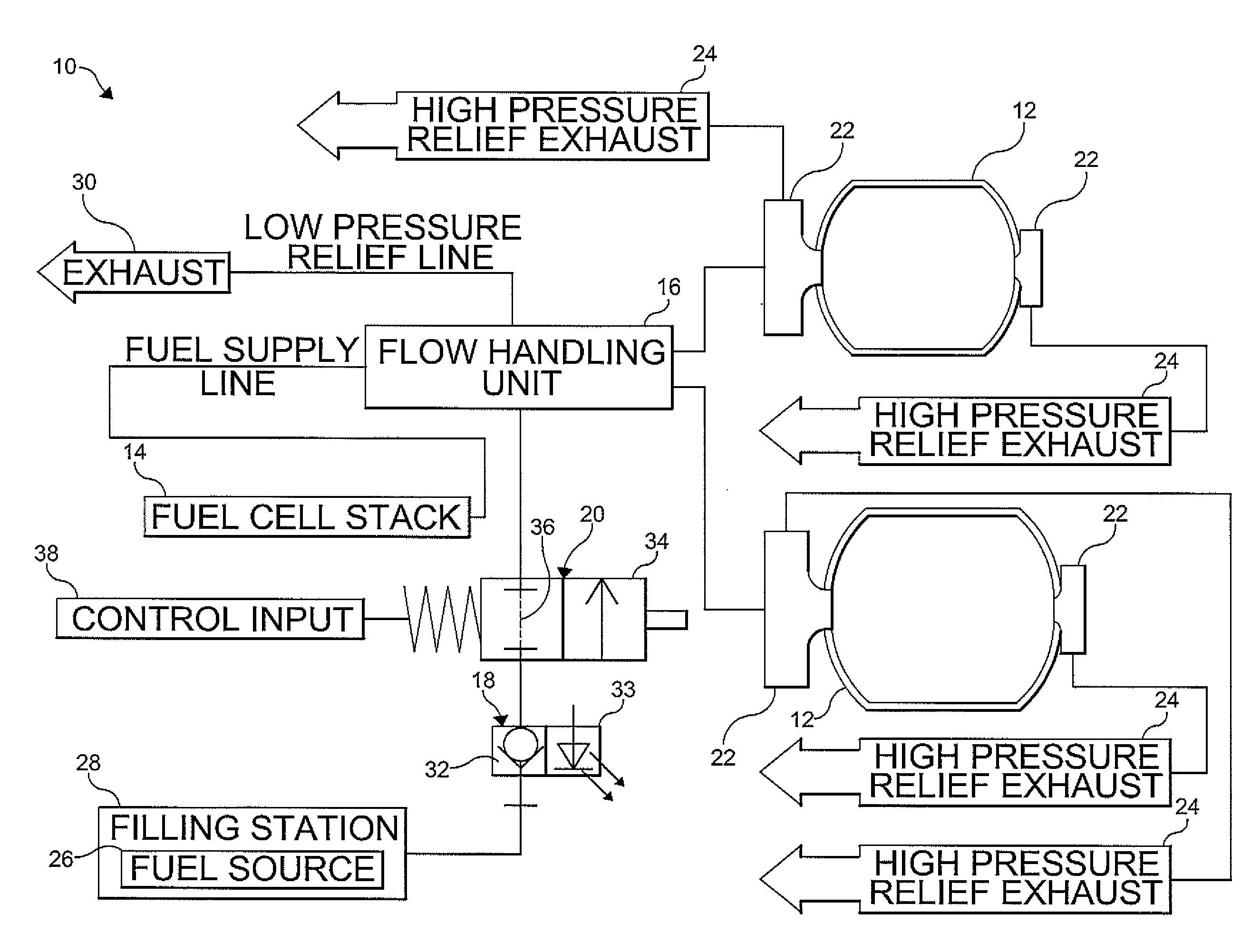
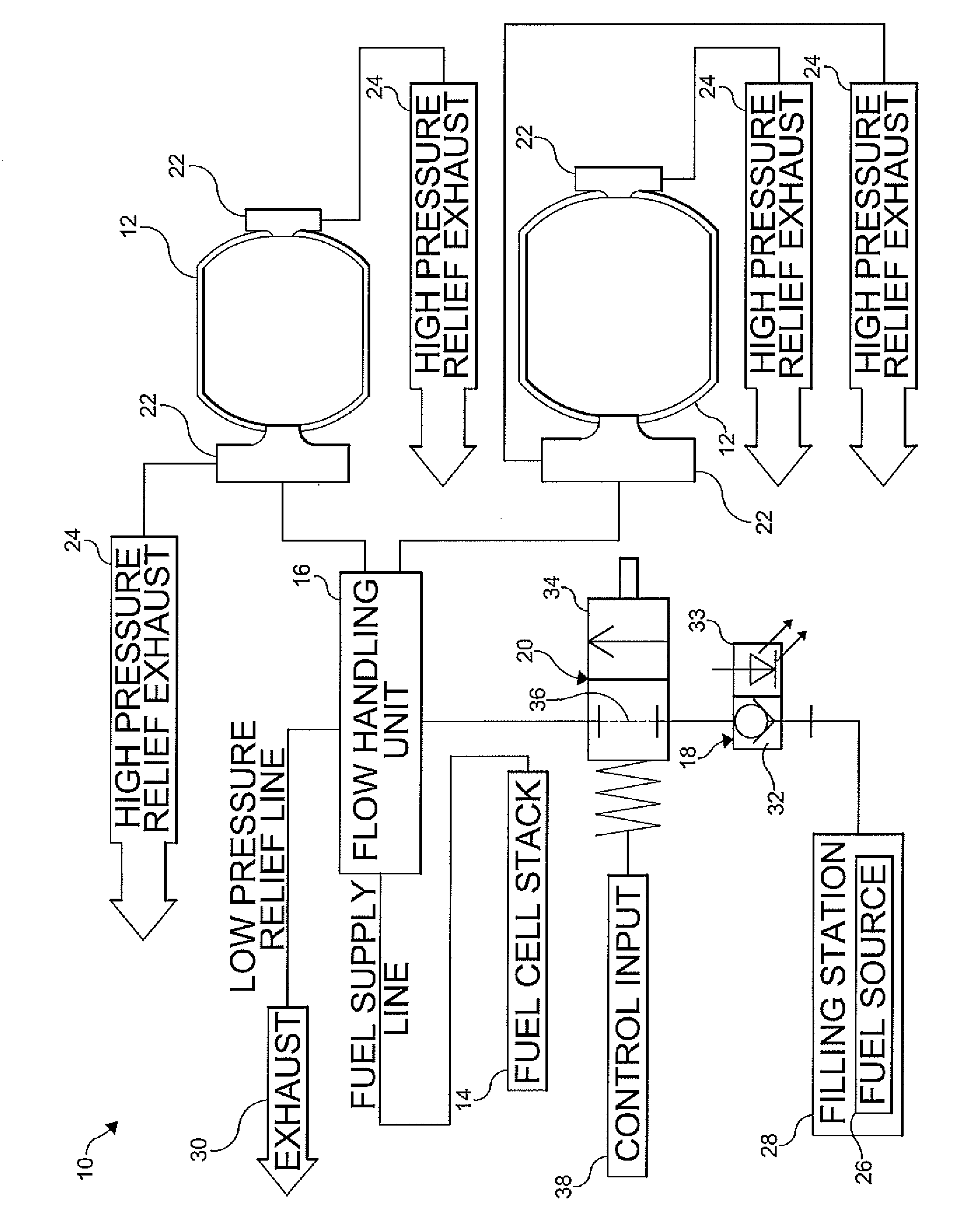
[0014]The drawing illustrates a fill control system 10 according to an embodiment of the present invention. As shown, the system 10 includes a pair of fuel storage vessels 12, a fuel cell stack 14 in fluid communication with each of the fuel storage vessels 12, a flow handling unit 16 (i.e. gas / fuel handling unit) in fluid communication with the fuel storage vessels 12 and the fuel cell stack 14, a fuel inlet 18 in fluid communication with the fuel handling unit 16, and a fill control valve 20 in fluid communication with the fuel inlet 18 and the fuel...


PUM

PropertyMeasurementUnit
Pressureaaaaaaaaaa
Flow rateaaaaaaaaaa
Pressure dropaaaaaaaaaa

Abstract

A fill control system includes a fuel storage vessel, a fuel inlet in fluid communication with the fuel storage vessel to provide fluid communication between a fuel source and the fuel storage vessel, and a fill control valve disposed between and in fluid communication with the fuel inlet and the fuel storage vessel, an actuation of the fill control valve causing a pressure level upstream thereof which emulates a full condition of the fuel storage vessel.

Description

FIELD OF THE INVENTION[0001]The present invention relates generally to a control valve for a fueling operation. In particular, the invention is directed to a control valve for a compressed hydrogen system and a method for fueling the compressed hydrogen system.BACKGROUND OF THE INVENTION[0002]Fuel cell power systems have been proposed as a clean, efficient and environmentally responsible power source for electric vehicles and various other applications. One type of fuel cell power system employs use of a proton exchange membrane (PEM) to catalytically facilitate a reaction of fuels (such as hydrogen) and oxidants (such as air or oxygen) into electricity. Typically, the fuel cell power system has more than one fuel cell that includes an anode and a cathode with the PEM therebetween. The anode receives the hydrogen gas and the cathode receives the oxygen. The hydrogen gas is ionized in the anode to generate free hydrogen ions and electrons. The hydrogen ions pass through the electroly...

Claims


Application Information

Patent Timeline
IPC IPC(8): B65B3/04B65B3/26
CPCY02E60/50H01M2008/1095H01M8/04753Y02E60/32B67D7/36F17C5/06F17C13/025F17C13/04
Inventor SCHULZE, JORG
Owner GM GLOBAL TECH OPERATIONS LLC
Why Eureka
Try Eureka