Heat exchanger and turbulator for the same

a technology of heat exchanger and turbulator, which is applied in the direction of heat transfer modification, lighting and heating apparatus, laminated elements, etc., can solve the problems of fluid turbulence performance degradation, and achieve the effect of reducing fluid flow resistance and improving productivity

Inactive Publication Date: 2012-08-02
SAM SUNG CLIMATE CONTROL
View PDF4 Cites 14 Cited by
  • Summary
  • Abstract
  • Description
  • Claims
  • Application Information

AI Technical Summary

Benefits of technology

[0017]An object of the present invention is to provide a heat exchanger and a turbulator for the heat exchanger, in which a heat exchanger is integrally manufactured in a novel structure with a desirable size, so that the productivity can be improved and the flow resistance of the fluid can be minimized.
[0026]As described above, since the turbulator for the heat exchanger according to the present invention can be arranged in a direction along which the crest and the valley are repeatedly formed along the flow direction of a fluid, the turbulator can be integrally manufactured regardless of a desirable length. Accordingly, the assembling processes of installing the turbulator can be reduced, so that the workability can be improved.

Problems solved by technology

However, in this case, the turbulence performance of the fluid may be degraded.

Method used


Image

  • Heat exchanger and turbulator for the same
  • Heat exchanger and turbulator for the same
  • Heat exchanger and turbulator for the same

Examples


Embodiment Construction

[0039]Hereinafter, a heat exchanger and a turbulator for the heat exchanger according to an exemplary embodiment of the present invention will be described with reference to FIGS. 2 to 14.

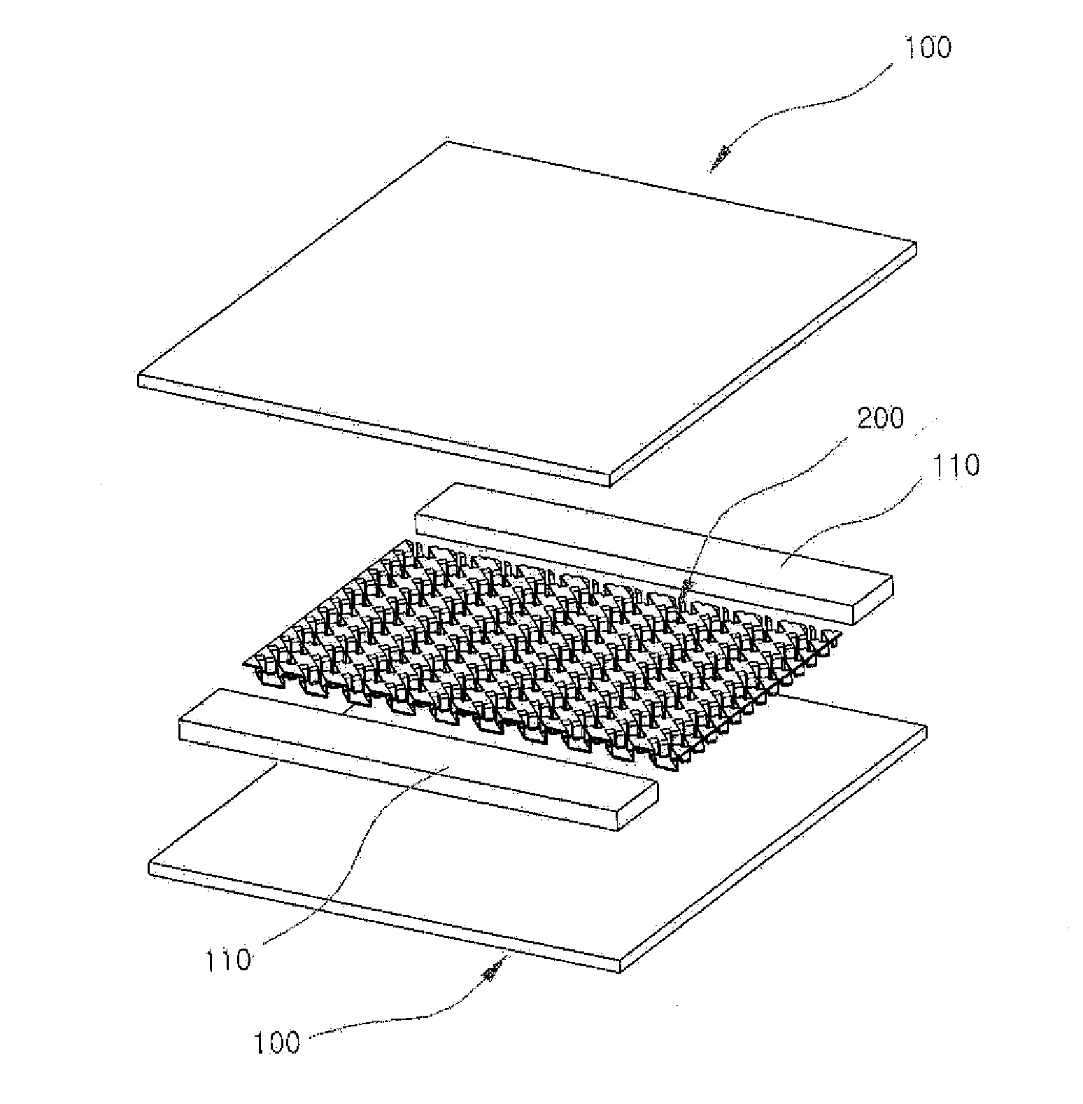
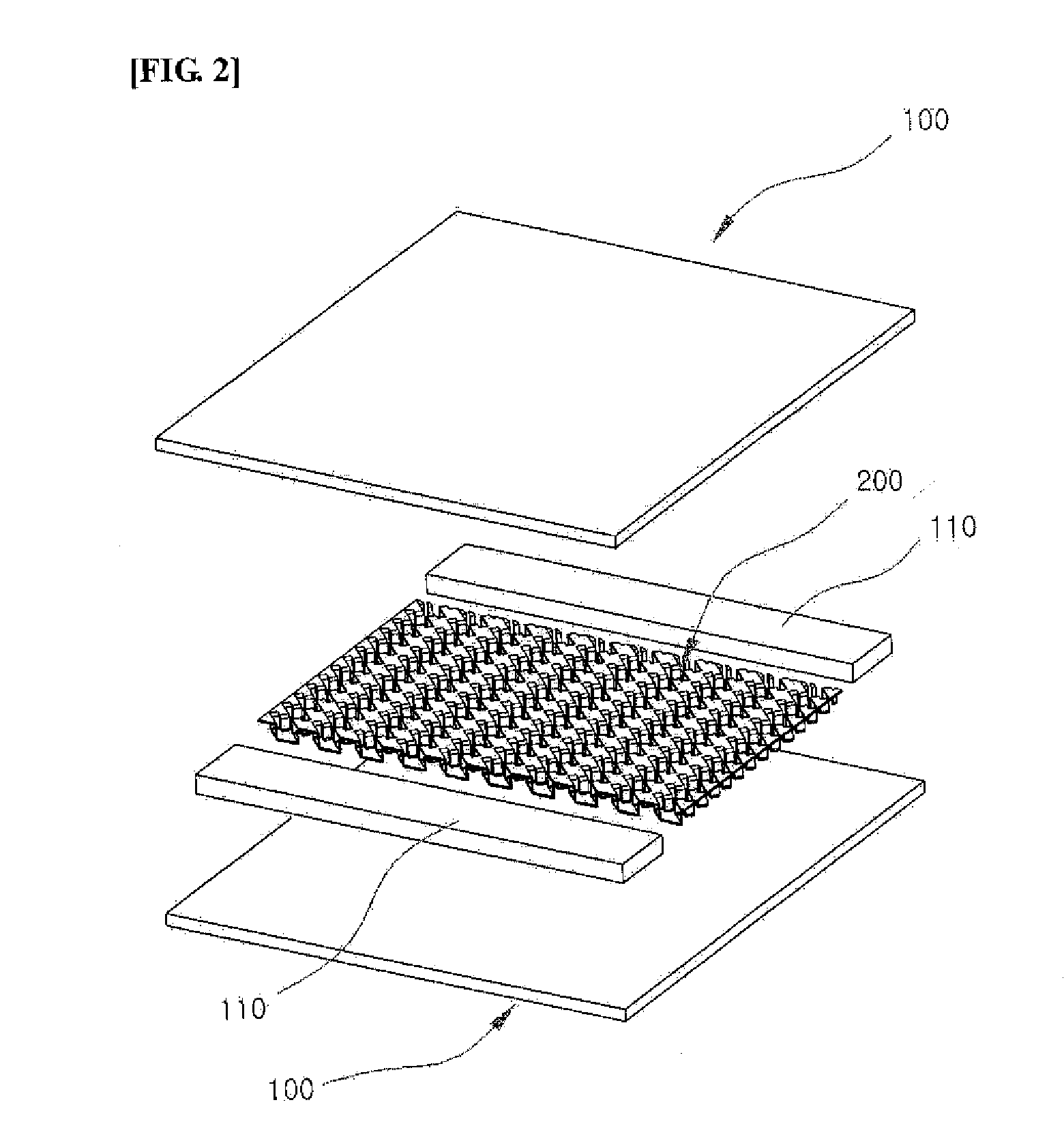
[0040]The heat exchanger according to the exemplary embodiment of the present invention includes a heat exchange plate 100 and a turbulator 200 as shown in FIG. 2.

[0041]The heat exchange plate 100 performs heat exchange with a fluid and guides the flow of the fluids. A plurality of heat exchange plates 100 are provided, and stacked on each other while being spaced apart from each other.

[0042]In addition, partition bars 110 are interposed between the heat exchange plates 100 corresponding to both side ends of the heat exchange plates 100 when viewed in the flow direction of a fluid, thereby uniformly maintaining the distance between the heat exchange plates 100 while defining the fluid passage.

[0043]In this case, two or three partition bars 110 may be provided according to the number of the fluid pa...


PUM


Abstract

Disclosed are a heat exchanger and a turbulator for the same. The heat exchanger is integrally manufactured in a novel structure with a desirable size, so that the productivity can be improved and the flow resistance of the fluid can be minimized. The turbulator for a heat exchanger includes a plurality of crests and a plurality of valleys that are repeatedly formed, and a plurality of bent ends formed on front and rear surfaces of each crest and inwardly bent while being repeatedly alternated in a direction along which the crest and the valley are repeatedly formed. A portion of each bent end is inclined left or right to form a through hole perforated in the direction along which the crest and the valley are repeatedly formed so that the fluid passes through the through hole.

Description

BACKGROUND OF THE INVENTION[0001]1. Field of the Invention[0002]The present invention relates to a heat exchanger and a turbulator for the same, in which the turbulator is integrally manufactured with a desirable size, so that fluid flow resistance can be minimized and the productivity can be improved.[0003]2. Description of the Related Art[0004]In general, a heat exchanger is a device to cool combustion heat and heat emitted when a fluid or air is compressed, or heat emitted from a rotational body.[0005]In other words, the heat exchanger has been employed to all application fields in which heat must be cooled or a temperature must be increased.[0006]In particular, in a heat exchanger according to the related art, a turbulator, which is separately manufactured, is interposed between heat exchange plates through which air and cooling water or oil pass while crossing each other, so that the air, the cooling water or the oil passing through each heat exchanging plate is turbulated. Acc...

Claims


Application Information

Patent Timeline
Patent Type & Authority Applications(United States)
IPC IPC(8): F28F13/12
CPCF28F13/12F28F3/027F28F3/02F28F3/12
Inventor CHOI, SUNG-OU
Owner SAM SUNG CLIMATE CONTROL
Why Eureka
Try Eureka