
Structure for reducing axial leakage of valve

a technology of axial leakage and structure, which is applied in the direction of spindle sealing, valve operating means/release devices, machines/engines, etc., can solve the problems of difficult or impossible to use a conventional ptfe or fluoroplastic-based shaft seal, difficult to suppress and the effect of reducing the amount of axial leakag

Inactive Publication Date: 2012-08-02
MITSUBISHI ELECTRIC CORP
View PDF8 Cites 24 Cited by
  • Summary
  • Abstract
  • Description
  • Claims
  • Application Information

AI Technical Summary

Benefits of technology

[0008]Therefore, when the axial leakage reducing structure disclosed in Patent Document 1 is used for a fluid having a high temperature (200° C. or more), the labyrinth seal as is can be used; however, it is necessary that the material of the lip seal be changed from PTFE to metal or a high-temperature resistant material. However, in this case, it is expected that the friction between the lip seal and the valve shaft is increased to interfere with the operation of the valve shaft itself, and that the seal structure at the gap with the valve shaft cannot be established; thus, it is difficult to reduce the axial leakage thereof under the high temperature. In addition, the above structure is applicable to the fluid having a low temperature (lower than 200° C.), but has an inferior sealing function as compared with the shaft seal of PTFE. Note that the cost can be reduced.
[0009]The present invention is made to solve the above-mentioned problems, and an object of the invention is to provide an axial leakage reducing structure for reducing the axial leakage of a valve.
[0011]According to the invention, since there is provided with the shaft seal section press-fitted on the outer peripheral surface of the valve shaft to be rotated with abutting against the surface of the bushing section on the side of the fluid passage by the pressurization acting on the valve shaft, the axial leakage reducing structure for a valve can be provided to reduce the axial leakage by eliminating the gap between the valve shaft and the shaft seal section and also the gap between the bushing section and the shaft seal section.

Problems solved by technology

However, since the high temperature gas flowing through an EGR valve reaches 200-800° C., and especially the high temperature gas flowing through a hot-side valve disposed immediately before an EGR cooler reaches as high as 800° C., it is difficult or impossible to use a conventional PTFE or fluoroplastic-based shaft seal due to the possibility of exceeding the heat resistant temperature thereof; thus, there is a problem such that it is difficult to suppress the amount of axial leakage.
For this reason, it is expected that the lip seal mainly plays the role of suppressing the axial leakage; however, since the lip seal is made of PTFE, the lip seal cannot be employed in a valve such that a hot temperature gas of 200-800° C. flows therethrough, as mentioned above, which makes it impossible to reduce the amount of axial leakage.
However, in this case, it is expected that the friction between the lip seal and the valve shaft is increased to interfere with the operation of the valve shaft itself, and that the seal structure at the gap with the valve shaft cannot be established; thus, it is difficult to reduce the axial leakage thereof under the high temperature.
), but has an inferior sealing function as compared with the shaft seal of PTFE.

Method used


Image

  • Structure for reducing axial leakage of valve
  • Structure for reducing axial leakage of valve
  • Structure for reducing axial leakage of valve

Examples


first embodiment

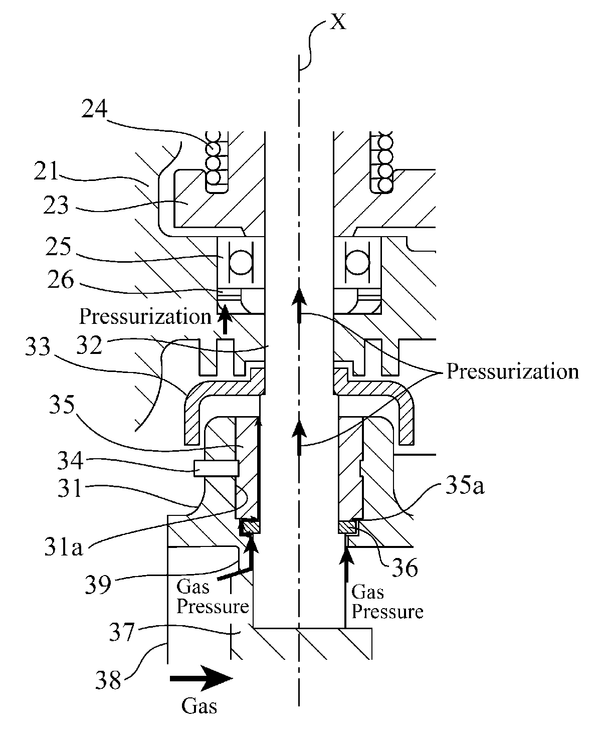
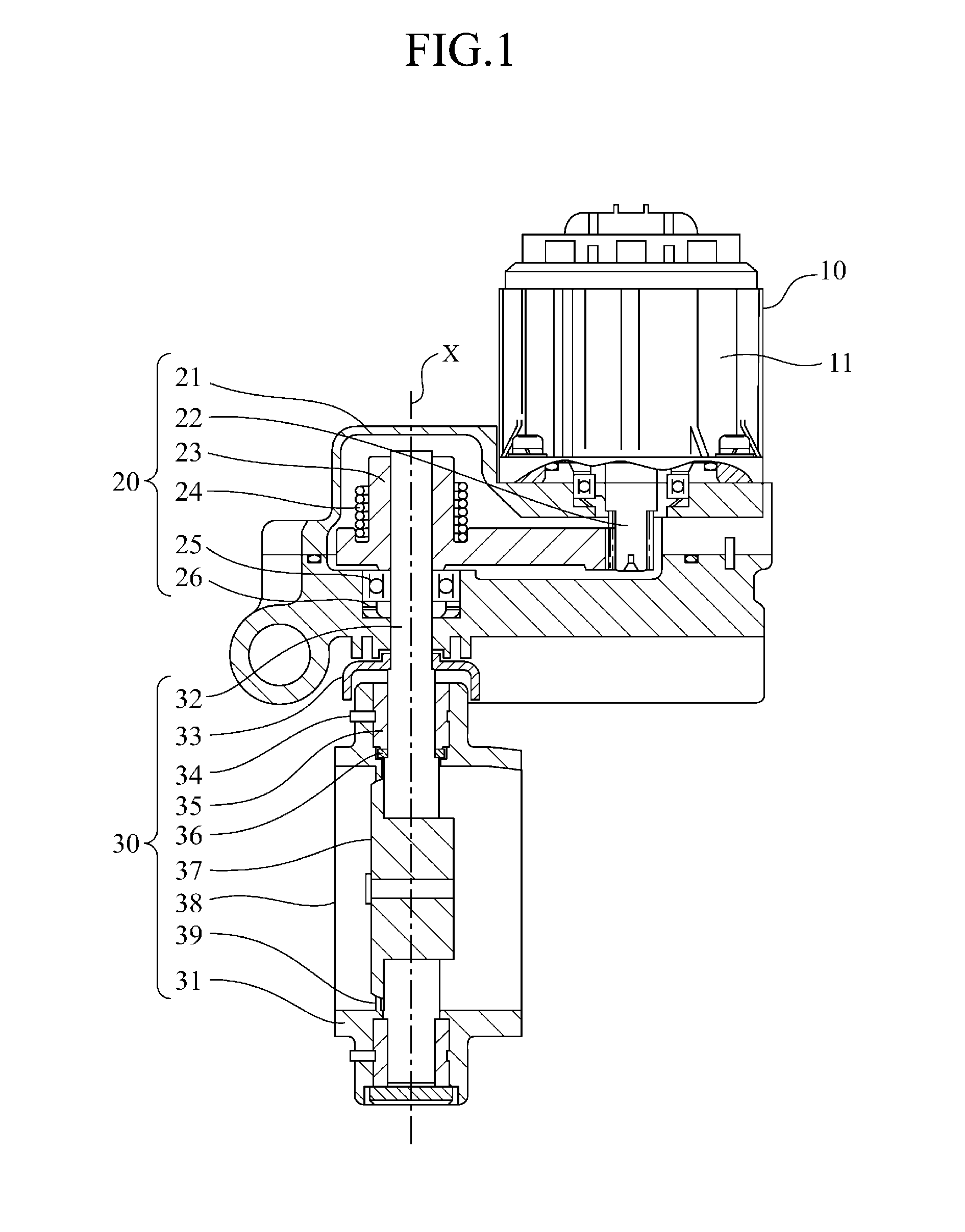
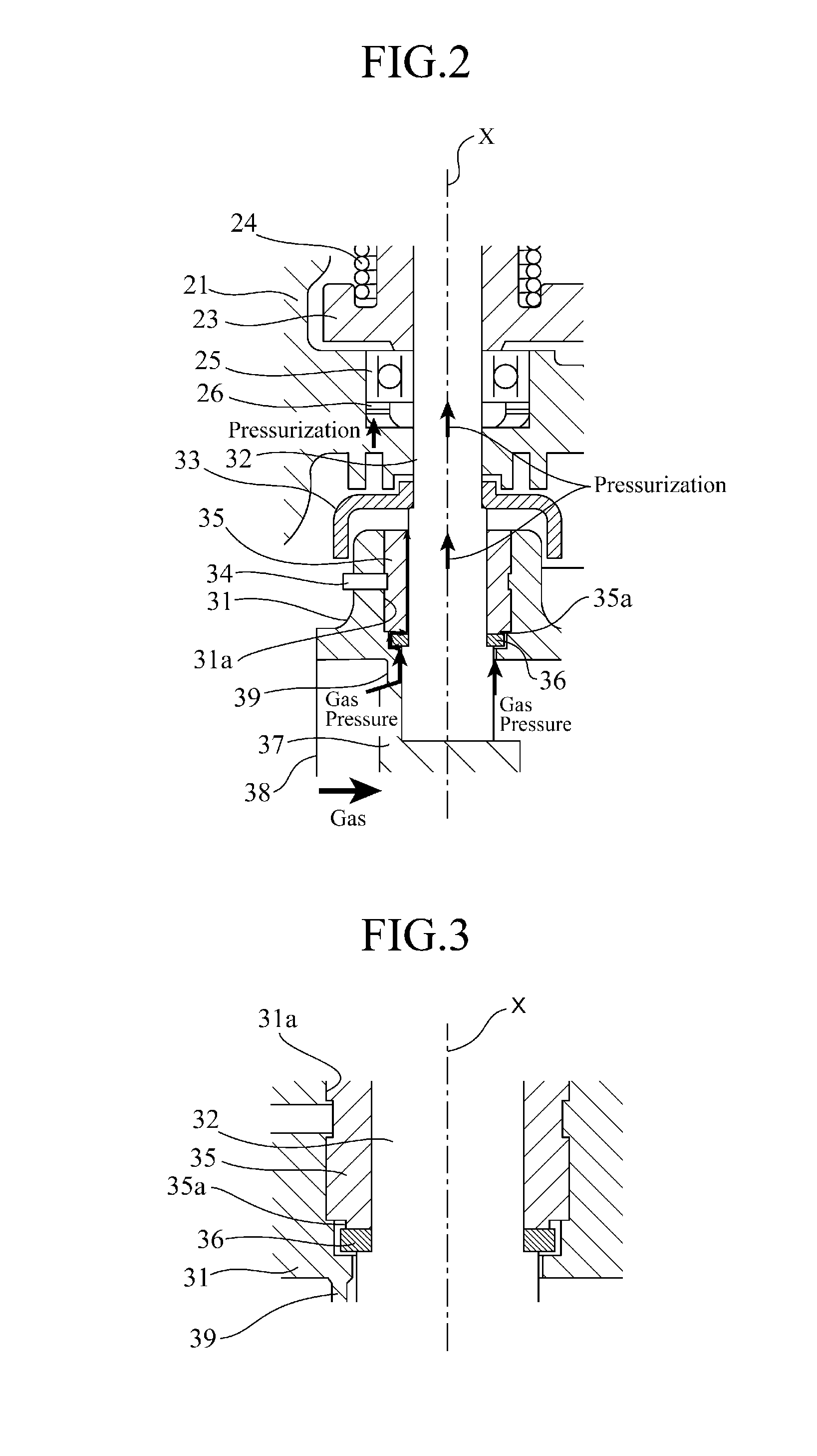
[0016]An EGR valve device shown in FIG. 1 is composed of an actuator section 10 for generating rotation driving force to open and close a valve; a gear section 20 for transmitting the driving force of the actuator section 10 to a rod (valve shaft) 32; and a valve section 30 interposed in a tube (not shown) to be flown through by a high-temperature exhaust gas to open and close a butterfly-valve-shaped valve (valve body) 37 to control the flow-through of the exhaust gas.

[0017]In the actuator section 10, a DC motor or the like is employed for a motor 11, and a pinion gear 22 located inside a gear section housing 21 is connected to one end of the driving shaft of the motor 11. When the motor 11 is driven, the pinion gear 22 and the gear 23 are rotated with meshing with each other to thereby transmit the driving force of the motor 11 to the rod 32. The rod 32 is pivotally supported to be rotatable by a bearing 25, and is rotated about the central axis of rotation X by the driving force ...


PUM


Abstract

A plate 36 is press-fitted on the outer peripheral surface of a rod 32 to eliminate a gap between the rod 32 and the plate 36, and further the pressurization produced by the pressure of gas leaking from a gas passage 38 and the load of a washer 26 is caused to act on the rod 32 to thereby positively abut the plate 36 united with the rod 32 against a bush 35.

Description

TECHNICAL FIELD[0001]The present invention relates to a structure for reducing the axial leakage in a fluid controlling valve such as an exhaust gas recirculation (EGR) valve.BACKGROUND ART[0002]With the enhancement of exhaust gas regulations associated with recent environmental problems, in order to reduce the emissions from an engine, it has been requisite to reduce the axial leakage in a valve such as an EGR valve through which a high temperature gas is flown.[0003]Conventionally, in a fluid controlling valve, in order to suppress the axial leakage where the fluid inside a fluid passage leaks through a gap between a housing or a bearing, bushing and a valve shaft, a shaft seal made of polytetrafluoroethylene (PTFE) or fluoroplastic or a labyrinth seal structure is provided in the gap. For example, in an axial leakage reducing structure disclosed in Patent Document 1, a labyrinth seal is provided around the outer periphery of a valve shaft on the side of the fluid passage of the b...

Claims


Application Information

Patent Timeline
IPC IPC(8): F16K41/00
CPCF02D9/106F02M25/0773Y02T10/121F02M25/0797F16K1/2268F02M25/0793F02M26/74F02M26/54F02M26/70F16K1/226
Inventor TAKAI, KATSUNORIHASEGAWA, SATORUYOKOYAMA, MASAYUKI
Owner MITSUBISHI ELECTRIC CORP
Features
  • Generate Ideas
  • Intellectual Property
  • Life Sciences
  • Materials
  • Tech Scout
  • Unparalleled Data Quality
  • Higher Quality Content
  • 60% Fewer Hallucinations
Learn More