Control device, electro-optical device, driving method for electro-optical device and electronic apparatus

a technology of electrooptical devices and driving methods, applied in the direction of electric digital data processing, instruments, computing, etc., can solve the problems of wasting power and likely generation of afterimages, and achieve the effect of high-quality display

Inactive Publication Date: 2012-08-02
SEIKO EPSON CORP
View PDF5 Cites 10 Cited by
  • Summary
  • Abstract
  • Description
  • Claims
  • Application Information

AI Technical Summary

Benefits of technology

[0006]The invention has been made in view of the circumstance described above, and it is an object of the invention to provide a technology that reduces such afterimages as described above, and enables high-quality display.

Problems solved by technology

However, in the differential drive, when the entire pixels are switched to white color, there is a problem in that an afterimage would likely be generated in the vicinity of a boundary between those of the pixels that continue to be white and those of the pixels that are switched from black to white.
However, this type of refresh drive wastes power.

Method used


Image

  • Control device, electro-optical device, driving method for electro-optical device and electronic apparatus
  • Control device, electro-optical device, driving method for electro-optical device and electronic apparatus
  • Control device, electro-optical device, driving method for electro-optical device and electronic apparatus

Examples


first embodiment

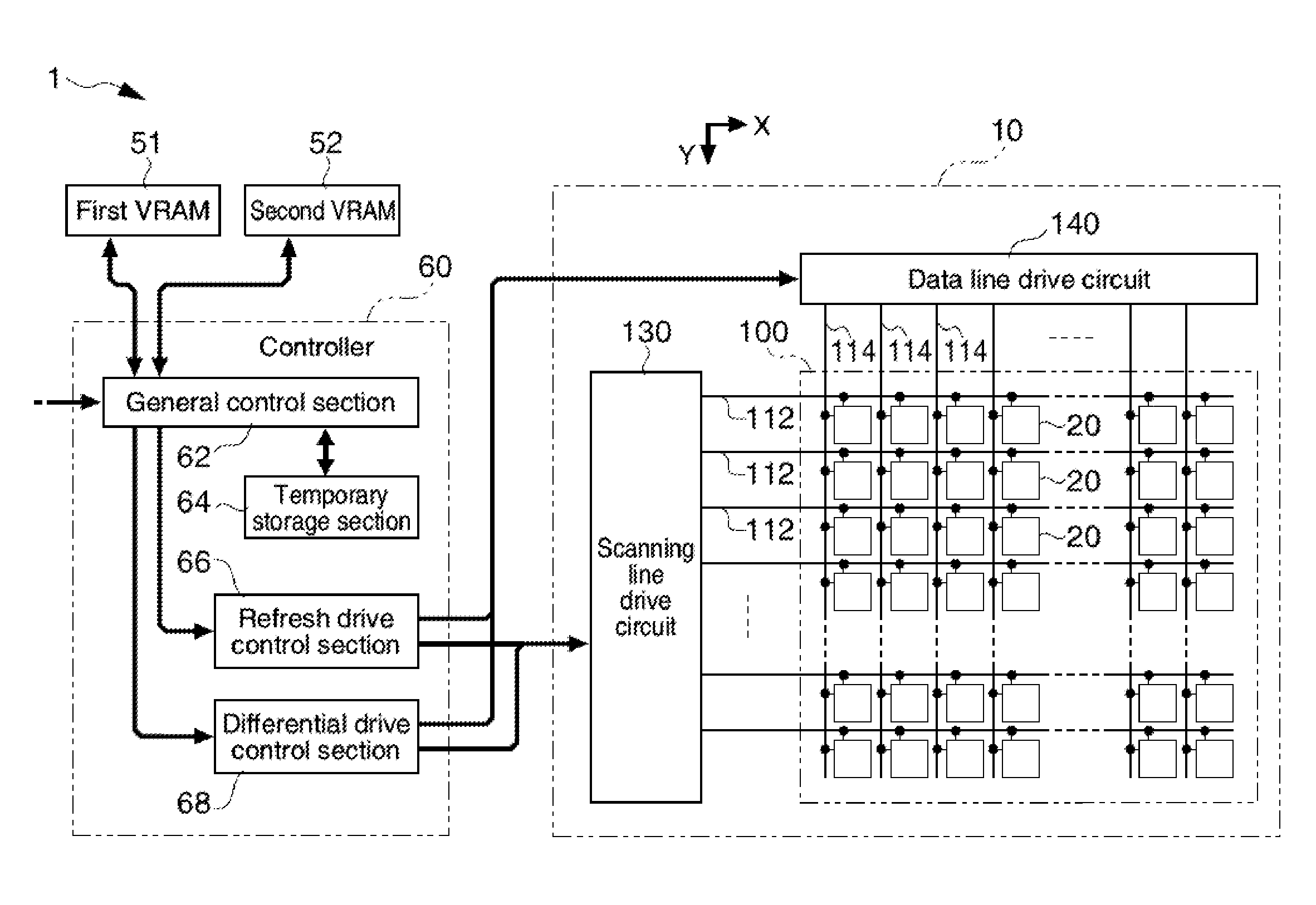
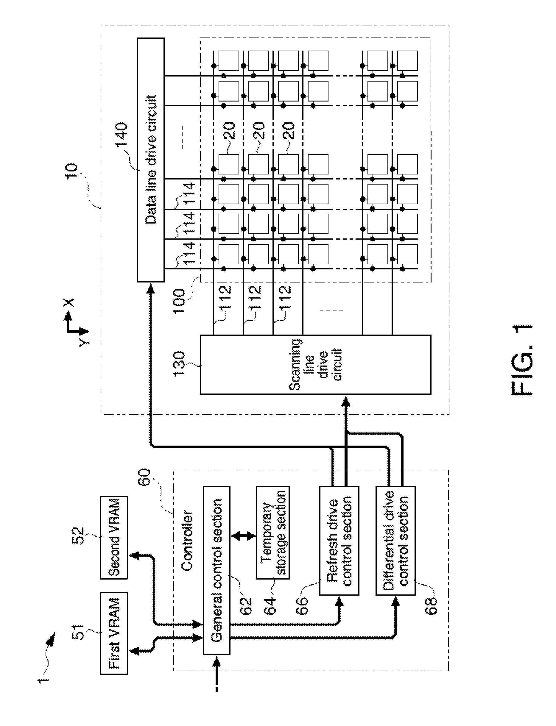
[0035]Embodiments of the invention will be described below with reference to the accompanying drawings. FIG. 1 is a block diagram showing an electrical configuration of an electro-optical device 1 in accordance with a first embodiment. As shown in FIG. 1, the electro-optical device 1 includes a display unit 10, a first VRAM 51, a second VRAM 52 and a controller 60.

[0036]The display unit 10 includes a plurality of scanning lines 112 provided along a row (X) direction, and a plurality of data lines 114 provided along a column (Y) direction in a manner to be electrically insulated from the scanning lines 112. Further, pixels 20 are provided at positions corresponding to intersections between the scanning lines 112 and the data lines 114. When the number of rows of the scanning lines 112 is “m” and the number of columns of the data lines 114 is “n,” for convenience sake, the pixels 20 form a display region 100 in which m rows in the vertical direction×n columns in the horizontal directi...

second embodiment

[0066]In the first embodiment described above, when the integrated value of counted sections where white pixels and black pixels are placed next to each other since the last refresh drive exceeds the threshold value Th1, a refresh drive is executed. For this reason, when changes occur multiple times in the display content, and the integrated value is less than the threshold value Th1, the refresh drive will not be executed. In this case, if the state in which white pixels and black pixels are placed next to each other at the same locations appears each time the display content is changed, afterimages remain at the same locations, and therefore their influence is believed to be small. However, in the first embodiment, if white pixels and black pixels are placed next to each other multiple times at the same locations, these locations are counted repeatedly, and there is a possibility that refresh drives may be frequently executed, which leaves room for improvement.

[0067]The second emb...

third embodiment

[0075]The cause of afterimages described above will be once again examined. When a white pixel and a black pixel are placed next to each other, the electric field on one of the pixels influences the other pixel, and therefore an afterimage is supposed to be generated at this moment. However, as long as the state in which the white pixel and the black pixel are next to each other is visually recognized in an emphasized manner, it is thought that the afterimage that is supposed to be occurring would in effect not be conspicuous. In other words, the afterimage becomes conspicuous not when the white pixel and the black pixel are placed next to each other, but when the two pixels in different colors placed next to each other transfer to the same color, and a color (afterimage) different from the color after transfer would exist, which is thought to make the afterimage conspicuous. In the first embodiment described above, occurrences in which white pixels and black pixels are placed next ...


PUM


Abstract

A control device for a display unit that includes pixels each having display elements is disclosed. The control device comprising a control unit counting sections where pixels with different gradations are placed next to each other in a predetermined region among an image to be displayed on the display unit. The control unit outputs an instruction to execute a refresh drive in the predetermined region when an integrated value of the sections exceeds a predetermined value.

Description

BACKGROUND[0001]1. Technical Field[0002]The present invention relates to technologies for reducing afterimages generated at outlines of displayed images.[0003]2. Related Art[0004]An electro-optical device using the memory-property of display elements such as electrophoretic elements, electronic powder-particle elements, and cholestric liquid crystal elements has been known. For the sake of simplicity of the description, let us assume that the display elements display binary values, for example, white color and black color. For example, when the entire pixels are switched to white color to perform an all-white display, a differential drive is executed. The differential drive uses the memory property of the display elements, in which white-displayed pixels in a preceding image are not driven, and black-displayed pixels other than white color in the preceding image are driven to be switched to white color (see, for example, JP-A-2007-206267).[0005]However, in the differential drive, wh...

Claims


Application Information

Patent Timeline
Patent Type & Authority Applications(United States)
IPC IPC(8): G09G5/10
CPCG02F1/167G09G3/20G09G3/344G09G3/36G09G3/34G09G2310/04G09G2320/0247G09G2320/0257G09G2330/021
Inventor MUTO, KOTAYAMADA, YUSUKE
Owner SEIKO EPSON CORP
Why Eureka
Try Eureka