Iris image definition estimation system using the astigmatism of the corneal reflection of a non-coaxial light source

astigmatism technology, applied in the field of iris image definition estimation system using the astigmatism of the corneal reflection of a non-coaxial light source, can solve the problems of inability to easily achieve real-time calculation of resolution, shallow depth of field of a telephoto lens, and inability to provide a single image focus adjustment direction, etc., to achieve the effect of simplifying the calculation

Active Publication Date: 2012-08-02
NAT CHIAO TUNG UNIV
View PDF1 Cites 112 Cited by
  • Summary
  • Abstract
  • Description
  • Claims
  • Application Information

AI Technical Summary

Benefits of technology

[0012]The present invention features an iris image definition estimation system using the astigmatism of the corneal reflection of a non-coaxial light source. With the aid of a non-coaxial light source, a single image can be used to determine both the

Problems solved by technology

However, the depth of the field of a telephoto lens is very shallow, and, therefore, only cameras with auto-focusing or guided focusing mechanism can produce a high resolution image for iris recognition.
Due to the extensive workload, a real-time calculation of the resolution cannot easily be achieved.
Though Park and Kim used a near coaxial light source to significantly reduce the time for calculation, their method of iris focusing estimation technology cannot provide a focus adjustment direction from a single image when the iris pattern is close to the focus distance.
Therefore, excess time has to be wasted in exploring the direction of focusing.
Moreover, the unpredictable head movements of a user also contributes to multiple errors during the process of auto focus and can dramatically increase the time required for image acquisition.
Nonetheless, the gradient intensity of the iris patterns varies from person to person, and as a result, no universal standards are available for a determinatio

Method used


Image

  • Iris image definition estimation system using the astigmatism of the corneal reflection of a non-coaxial light source
  • Iris image definition estimation system using the astigmatism of the corneal reflection of a non-coaxial light source
  • Iris image definition estimation system using the astigmatism of the corneal reflection of a non-coaxial light source

Examples


Embodiment Construction

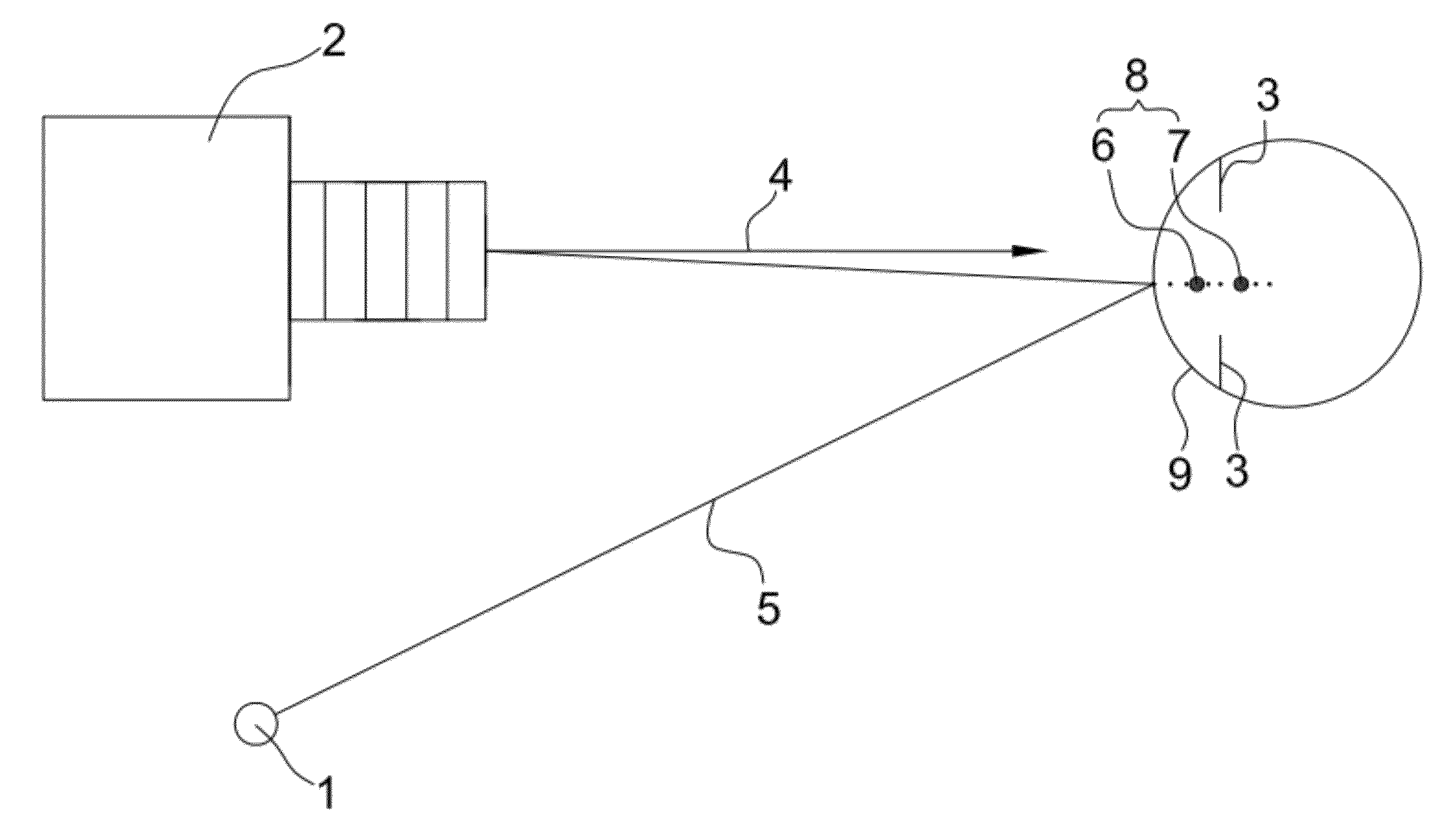
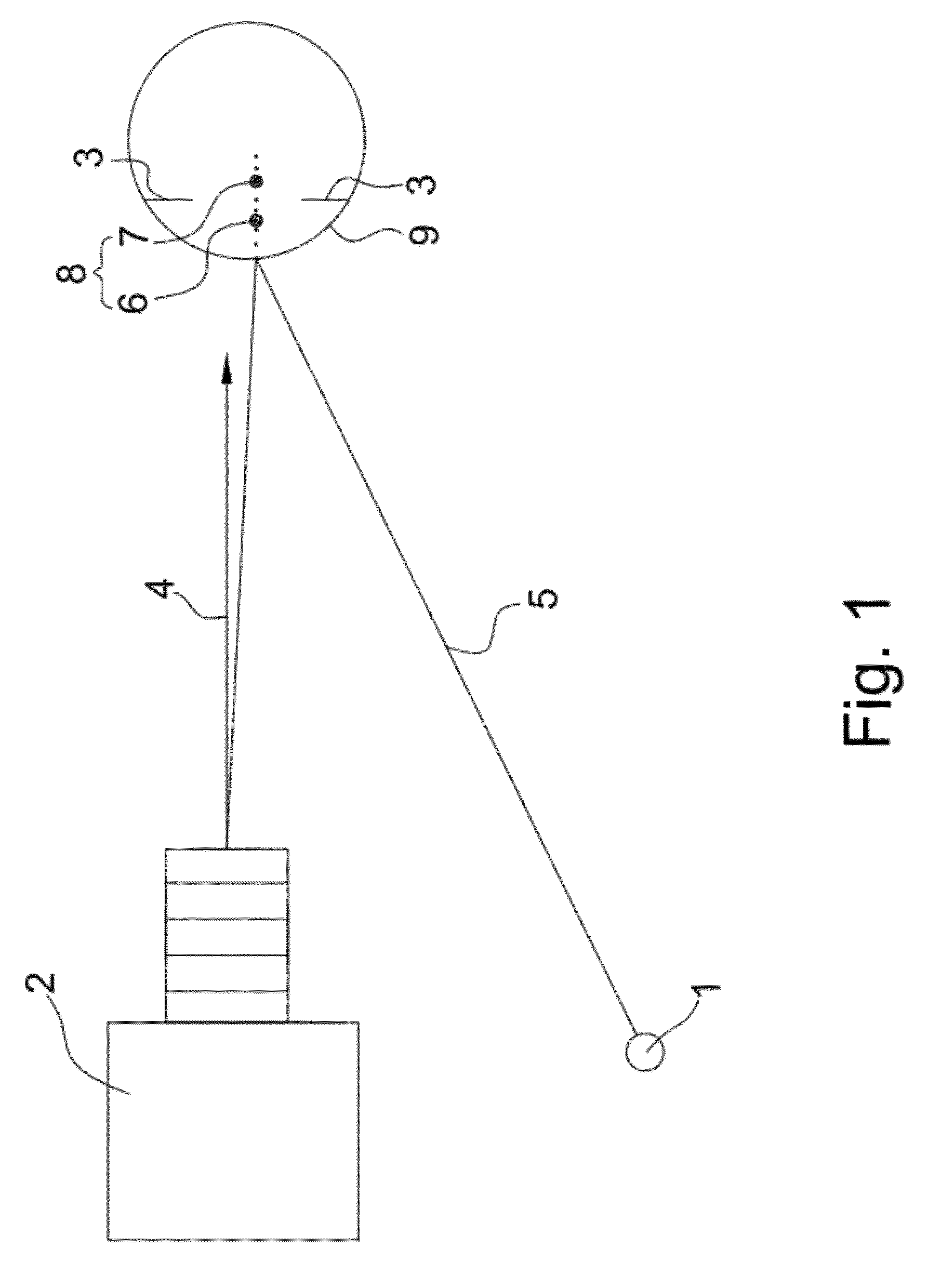
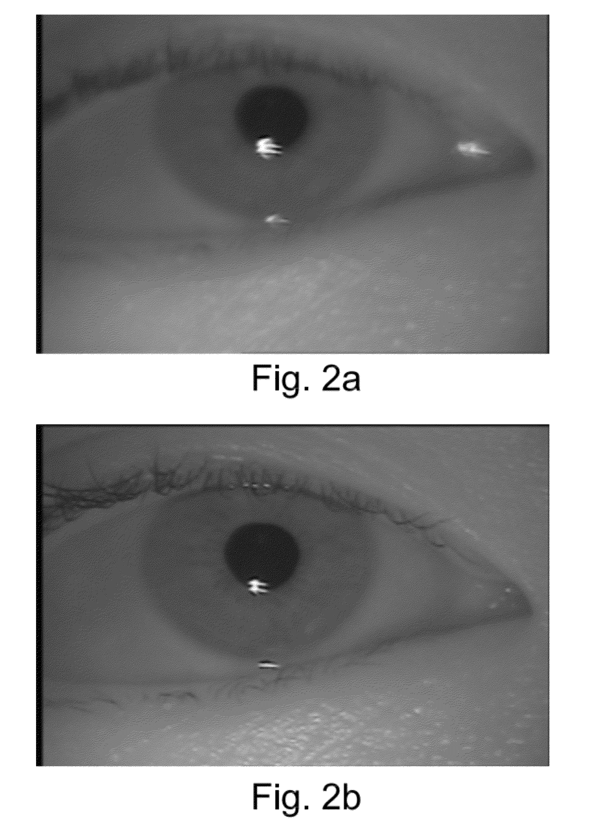
[0024]As shown in FIG. 1, the present invention provides an iris image definition estimation system using astigmatism of the corneal reflection of a non-coaxial light source which further comprises a non-coaxial light source 1, which is used to produce an incident light 5. Incident light 5 is transmitted into cornea 9 at an oblique angle deviating from the optical axis 4. The meridional virtual image 6 and the sagittal virtual image 7 are then formed behind the cornea due to astigmatism of the corneal reflection. An image sensor 2 records the composite glint area formed by both the meridional virtual image 6 and the sagittal virtual image 7, and subsequently provides the information for adjustment of the focus setting. If the sensor 2 focuses at a distance near the meridional virtual image 6, the glint area spreads narrowly along the meridional direction because it is clearly focused. On the other hand, if the sensor 2 focuses at a distance near the sagittal virtual image 7, the gli...


PUM


Abstract

An iris image definition estimation system using the astigmatism of the corneal reflection of a non-coaxial light source to assess both the resolution of the iris patterns and the direction of focus adjustment. The corneal reflection results in two virtual images on the meridional and the sagittal planes. These virtual images are formed behind the cornea and close to the iris. Yet, both are projected onto the same location and result in a composite glint area. In addition, the shape of the glint area of a non-coaxial light source varies with different camera focus settings. Furthermore, due to the high intensity of the glint area, the shape can be easily observed, and the size and the shape of the glint area can be used to determine the resolution of the iris image and the direction of focus adjustment, respectively.

Description

BACKGROUND OF THE INVENTION[0001]1. Field of the Invention[0002]The present invention relates to an iris image definition estimation system using the astigmatism of the corneal reflection of a non-coaxial light source. More specifically, the present invention relates to a system using the astigmatism of the corneal reflection of a non-coaxial source to produce two virtual images of the light source on the meridional and sagittal image planes, and utilizes the shape of the composite virtual images to determine the resolution of an iris image and the direction of focus adjustment.[0003]2. Description of the Prior Art[0004]The iris is a complex structure in the eye and is a fibrous membrane consisting of an anterior layer of stroma and a posterior layer of epithelia cells. In general, the stroma layer has many unique features (e.g. crypts, collaret, and pupillary ruffs, etc.) around the pupil. The unique nature of the iris results in a set of binary features with more than 240 degrees ...

Claims


Application Information

Patent Timeline
IPC IPC(8): A61B3/14
CPCA61B3/14
Inventor SHIH, SHENG-WEN
Owner NAT CHIAO TUNG UNIV
Why Eureka
Try Eureka