Systems and Methods for High Speed Power Factor Correction

Inactive Publication Date: 2012-08-02
WRATHALL ROBERT STEPHEN
View PDF5 Cites 7 Cited by
  • Summary
  • Abstract
  • Description
  • Claims
  • Application Information

AI Technical Summary

Benefits of technology

[0022]Systems and methods described herein provide for high speed power factor correction which can overcome or substantially alleviate the problems associated with changes in the operating conditions of a load or other transient events. The present technology senses the present state of a signal to quickly and accurately determine the presence of an overtone component within the signal. Rather than measuring the actual value of the overtone component,

Problems solved by technology

As such, this higher apparent power is subject to losses in the power generation and distribution processes.
This places a heavy stress on the power supply source 100 and the power distribution system 140, and may require more expensive generation and distribution equipment.
However, the transient response performance due to the delay introduced by the adaptive feedback loop continues to limit the overall power factor correction performance.
Due to t

Method used


Image

  • Systems and Methods for High Speed Power Factor Correction
  • Systems and Methods for High Speed Power Factor Correction
  • Systems and Methods for High Speed Power Factor Correction

Examples


Embodiment Construction

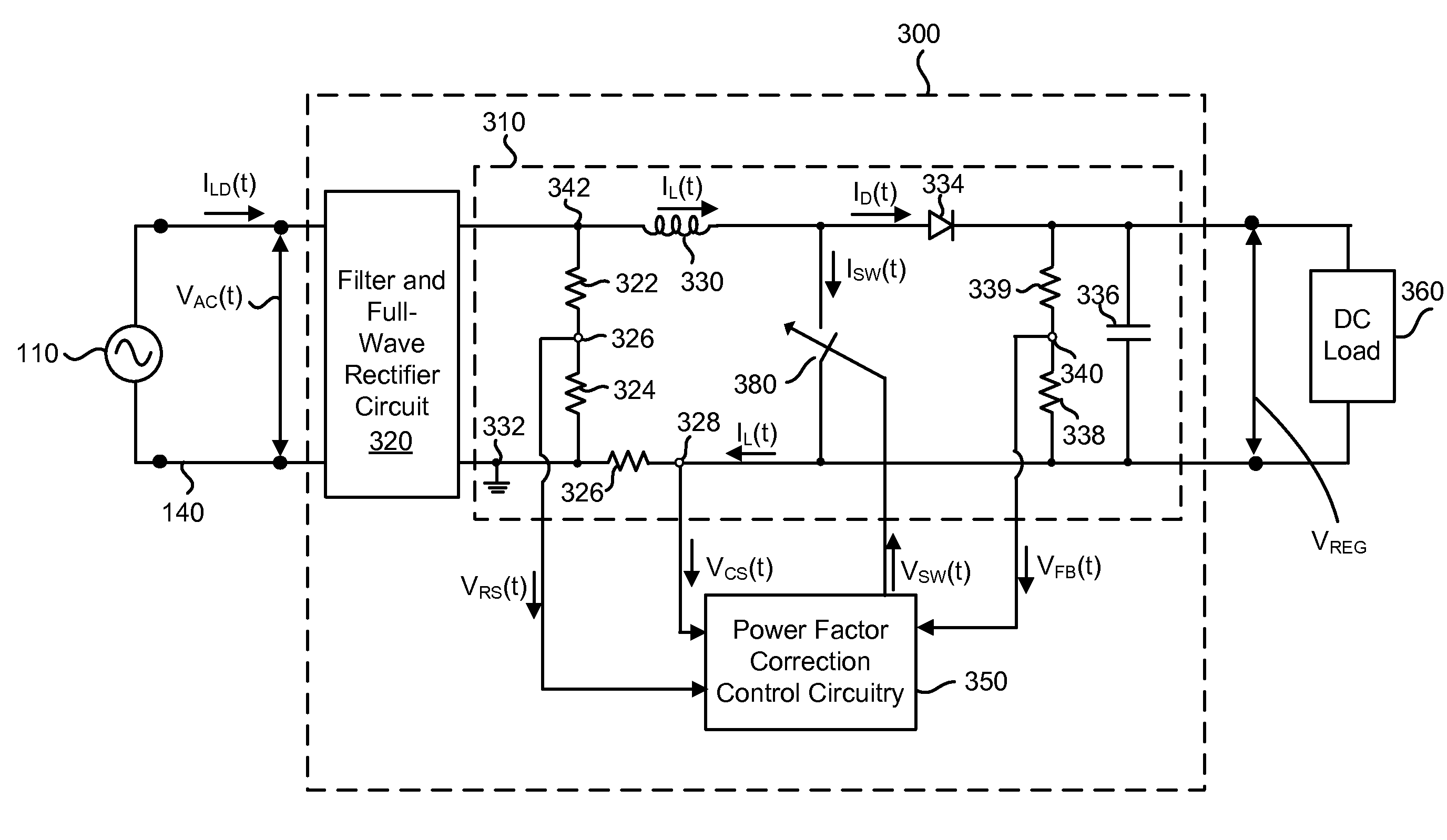
[0041]Systems and methods described herein provide for high speed power factor correction which can overcome or substantially alleviate the problems associated with changes in the operating conditions of a load or other transient events. The present technology senses the present state of a signal to quickly and accurately determine the presence of an overtone component within the signal. Rather than measuring the actual value of the overtone component, an expected value of the overtone component is determined based on the sensed state of the signal. Power factor correction is then performed to suppress the overtone utilizing a control signal formed based on the expected value of the overtone. By performing power factor correction based on the expected value, the present technology can provide high speed power factor correction which is not limited by the delay introduced by an adaptive feedback loop.

[0042]The expected value of the overtone component may be determined utilizing previ...


PUM


Abstract

Systems and methods described herein provide for high speed power factor correction which can overcome or substantially alleviate the problems associated with changes in the operating conditions of a load or other transient events. The present technology senses the present state conditions of a signal to quickly and accurately determine the presence of an overtone component within the signal. The expected value of the overtone component is then determined based on the sensed state of the signal. Power factor correction is then performed to suppress the overtone utilizing a control signal formed based on the expected value of the overtone. By performing power factor correction based on the expected value, the present technology can provide high speed power factor correction which is not limited by the delay introduced by an adaptive feedback loop.

Description


Claims


Application Information

Patent Timeline
Owner WRATHALL ROBERT STEPHEN
Why Eureka
Try Eureka