Control apparatus and control method for internal combustion engine

a control apparatus and control method technology, applied in the direction of electrical control, process and machine control, instruments, etc., can solve the problems of deteriorating startability, emissions, fuel consumption, and inability to determine the fuel property, etc., to achieve accurate and rapid determination of the fuel property

Inactive Publication Date: 2011-12-08
TOYOTA JIDOSHA KK
View PDF10 Cites 18 Cited by
  • Summary
  • Abstract
  • Description
  • Claims
  • Application Information

AI Technical Summary

Benefits of technology

[0005]The invention provides a control apparatus and a control method for an internal combustion engine, which accurately and quickly determine a property of fuel at a time of start of the engine (during cranking before the engine starts to autonomously operate).

Problems solved by technology

However, the above-described apparatus cannot determine the fuel property until after normal operation (combustion) of the engine starts.
Therefore, the apparatus cannot set a fuel amount and / or an ignition timing to an appropriate value(s) according to the fuel property during a period from an engine start time until the fuel property is determined.
This may deteriorate startability, emissions, and fuel consumption.

Method used


Image

  • Control apparatus and control method for internal combustion engine
  • Control apparatus and control method for internal combustion engine
  • Control apparatus and control method for internal combustion engine

Examples


first embodiment

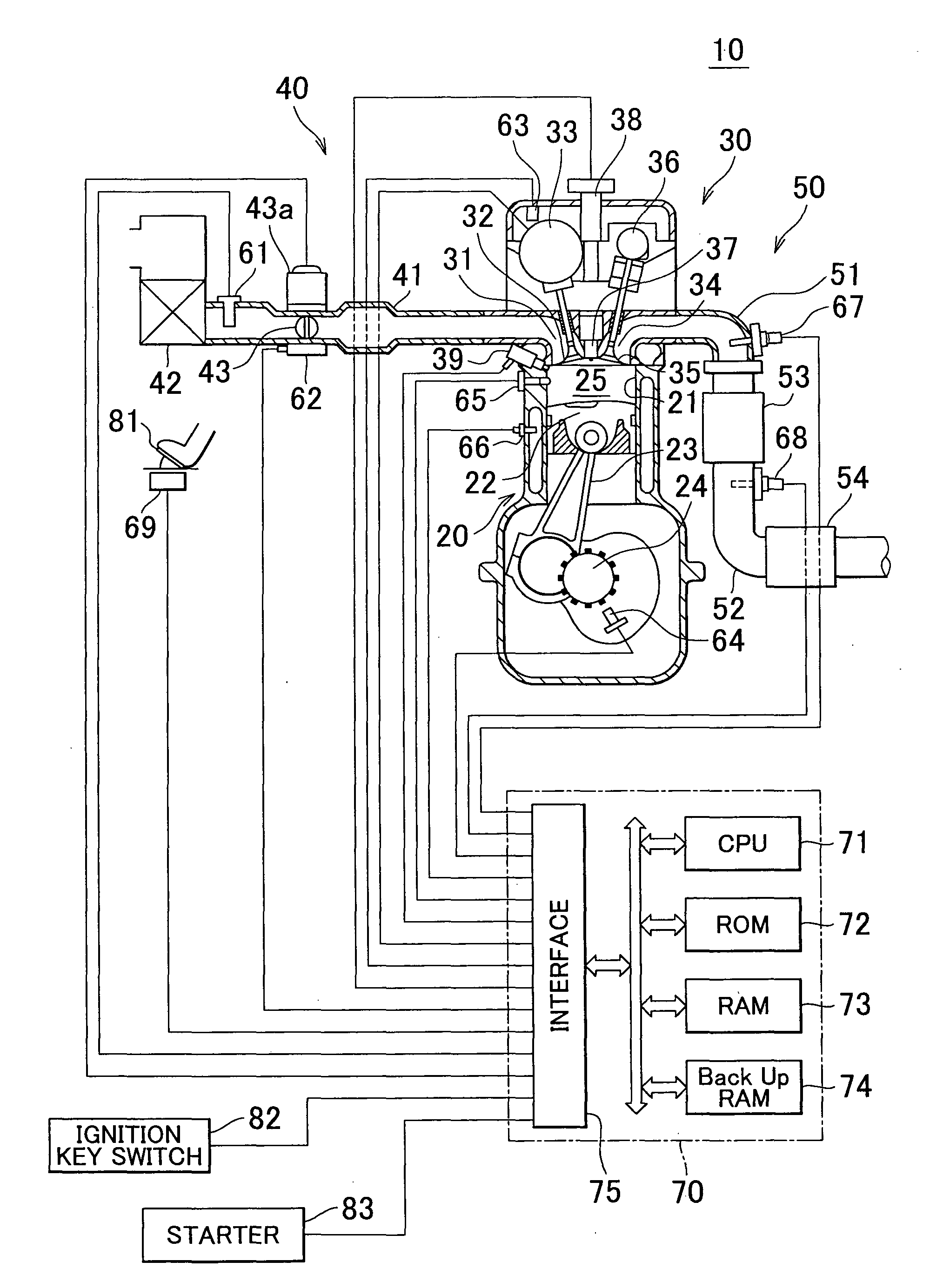
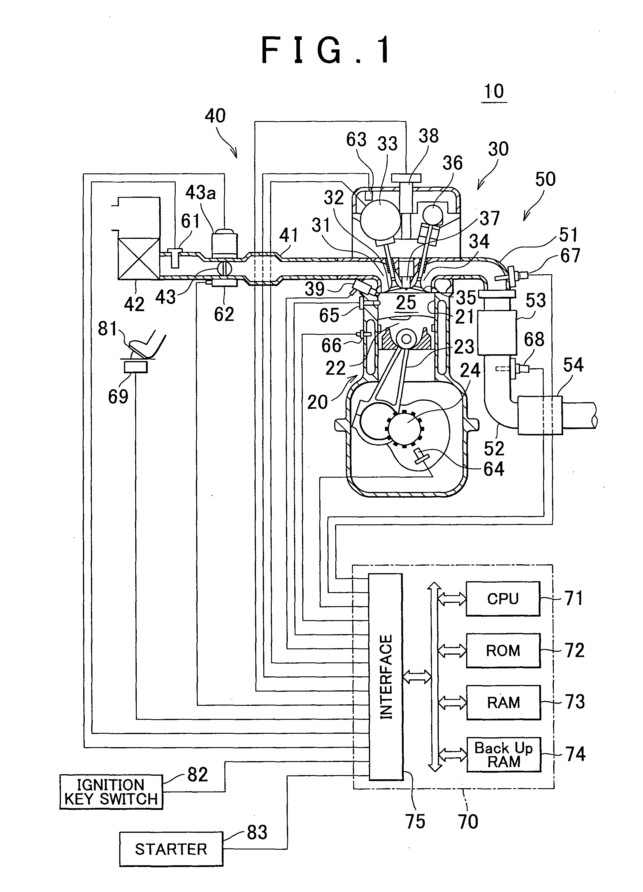
[0051]FIG. 1 is a diagram schematically showing a configuration of a system in which a control apparatus for an internal combustion engine according to a first embodiment of the invention is applied to a spark-ignition multi-cylinder (four-cylinder) four-cycle internal combustion engine 10 with a reciprocating piston using gasoline. Although FIG. 1 shows a sectional view of one cylinder, the other cylinders have the same configuration. The engine 10 is stably operated when fuel contains alcohol such as ethanol.

[0052]The internal combustion engine 10 includes a cylinder block portion 20 that includes a cylinder block, a cylinder block lower case, and an oil pan; a cylinder head portion 30 fixed on the cylinder block portion 20; an intake system 40 for supplying an air-fuel mixture to the cylinder block portion 20; and an exhaust system 50 for discharging exhaust gas from the cylinder block portion 20 to the outside.

[0053]The cylinder block portion 20 includes a cylinder 21, a piston ...

second embodiment

[0141]Next, a control apparatus for an internal combustion engine according to a second embodiment of the invention (hereinafter, may be referred to as “second control apparatus”) will be described. The throttle valve 43 of the second control apparatus is connected to the accelerator pedal 81 by a wire so that the throttle valve 43 is operated according to an operation of the accelerator pedal 81. Further, the second control apparatus includes a bypass passage that bypasses the throttle valve 43; and a known idling speed control valve (hereinafter, referred to as “ISC valve”) provided in the bypass passage. The bypass passage constitutes a part of the intake passage. The ISC valve changes an opening sectional area of the bypass passage (accordingly, a gross sectional area of the intake passage) according to an instruction signal from the CPU 71 of the second control apparatus. That is, the ISC valve is driven so that the opening amount of the ISC valve is equal to a target ISC valve...


PUM


Abstract

In a control apparatus, when an engine is cranked, “an air-fuel mixture (an air-fuel mixture used for determination of fuel property) including fuel in a first predetermined fuel amount TAUm and air in a first predetermined air amount Mcm”, which generates torque that does not make the engine autonomously operate, is formed in a first cylinder (cylinder used for determination of the fuel property), and the air-fuel mixture is ignited and combusted by a spark at an ignition timing after a compression top dead center. Further, the control apparatus determines “an amount of heat generated per unit mass of the fuel” when the air-fuel mixture is combusted in the first cylinder, and determines a property of the fuel based on the amount of generated heat.

Description

BACKGROUND OF THE INVENTION[0001]1. Field of the Invention[0002]The invention relates to a control apparatus and a control method for an internal combustion engine, which determine a property of fuel (fuel property) that changes according to, for example, a concentration of alcohol contained in the fuel supplied to the internal combustion engine.[0003]2. Description of the Related Art Japanese Patent Application Publication No. 1-88153 (JP-A-1-88153) describes an apparatus that detects a pressure in a cylinder (cylinder pressure) Pc (θ) with respect to a crank angle θ during “a compression stroke and an expansion stroke” in one combustion cycle, determines the amount of heat generated by combustion in one combustion cycle based on the detected pressure Pc (θ) and the volume Vc (θ) of a combustion chamber with respect to the crank angle θ, and determines a fuel property based on the determined amount of generated heat.[0004]However, the above-described apparatus cannot determine the ...

Claims


Application Information

Patent Timeline
Patent Type & Authority Applications(United States)
IPC IPC(8): F02D41/30F02D28/00
CPCF02B23/104F02B2075/125F02D13/0238F02D35/023F02D41/0025Y02T10/36F02D2200/0612Y02T10/123F02D19/061F02D19/084F02D19/088F02D41/009Y02T10/12Y02T10/30
Inventor MORIYA, HIDENORIYASUDA, HIROMICHITADOKORO, RYOOGINO, RYUSUKE
Owner TOYOTA JIDOSHA KK
Why Eureka
Try Eureka