Drywell retrofit sump insert for storm water treatment

a technology for storm water treatment and sump inserts, which is applied in the direction of sewage draining, separation processes, agriculture, etc., can solve the problems of affecting the function of drywells, affecting the service life of drywells, and unable to convey storm water from developed properties to municipal storm sewer systems, etc., to achieve the effect of convenient placemen

Inactive Publication Date: 2012-08-02
HARDGRAVE GRANT MICHAEL
View PDF41 Cites 13 Cited by
  • Summary
  • Abstract
  • Description
  • Claims
  • Application Information

AI Technical Summary

Benefits of technology

[0012]The present invention is a drywell retrofit sump insert that is inserted inside the chamber of an existing drywell. The drywell retrofit insert simultaneously provides treatment of the entering storm water by two means. The first is that it creates a settling chamber for sand, grit, and other heavier-than-water particles to settle out and collect in the sump of the insert. The second treatment mechanism is the oil baffles on the outlet holes which trap most of the oil, grease, and other lighter-than-water hydrocarbons inside the retrofit insert. After this treatment by the retrofit insert, the water flows through the outlet holes to the annular space between the exterior face of the insert and the interior face of the drywell. The treated storm water is then able to pass through the perforations in the drywell chamber and percolate into the surrounding native soils. The drywell insert is comprised of a rigid cylinder whose diameter is roughly six inches less than the inside diameter of the existing drywell. This allows an annular space of roughly three inches around the circumference of the retrofit insert. The insert has a solid flange attached to its bottom by a watertight joint. The top of the insert cylinder has no lid or flange, in order that it may freely receive the storm water that falls into the drywell chamber through its grated lid. For those drywells that also receive storm water from an underground pipe, the sump insert can be fabricated with an optional pipe inlet stub. A pair of lifting lugs at the top of the insert cylinder facilitates its placement into the existing drywell chamber with a crane.

Problems solved by technology

In many parts of the country, there are no municipal storm sewer systems to convey storm water from a developed property to natural water bodies such as rivers and lakes.
This polluted storm water is then infiltrated into the native soils and recharges the groundwater, potentially contaminating local drinking water supplies.
In addition to the groundwater contamination issue, silt and sand washed into a drywell will settle out of the storm water and collect in the bottom of the chamber.
Over time the function of the drywell can be impeded and eventually cease altogether if the pores in the adjacent native soils are plugged with silt.
This failure of the drywell can result in localized flooding and property damage.

Method used


Image

  • Drywell retrofit sump insert for storm water treatment
  • Drywell retrofit sump insert for storm water treatment
  • Drywell retrofit sump insert for storm water treatment

Examples


Embodiment Construction

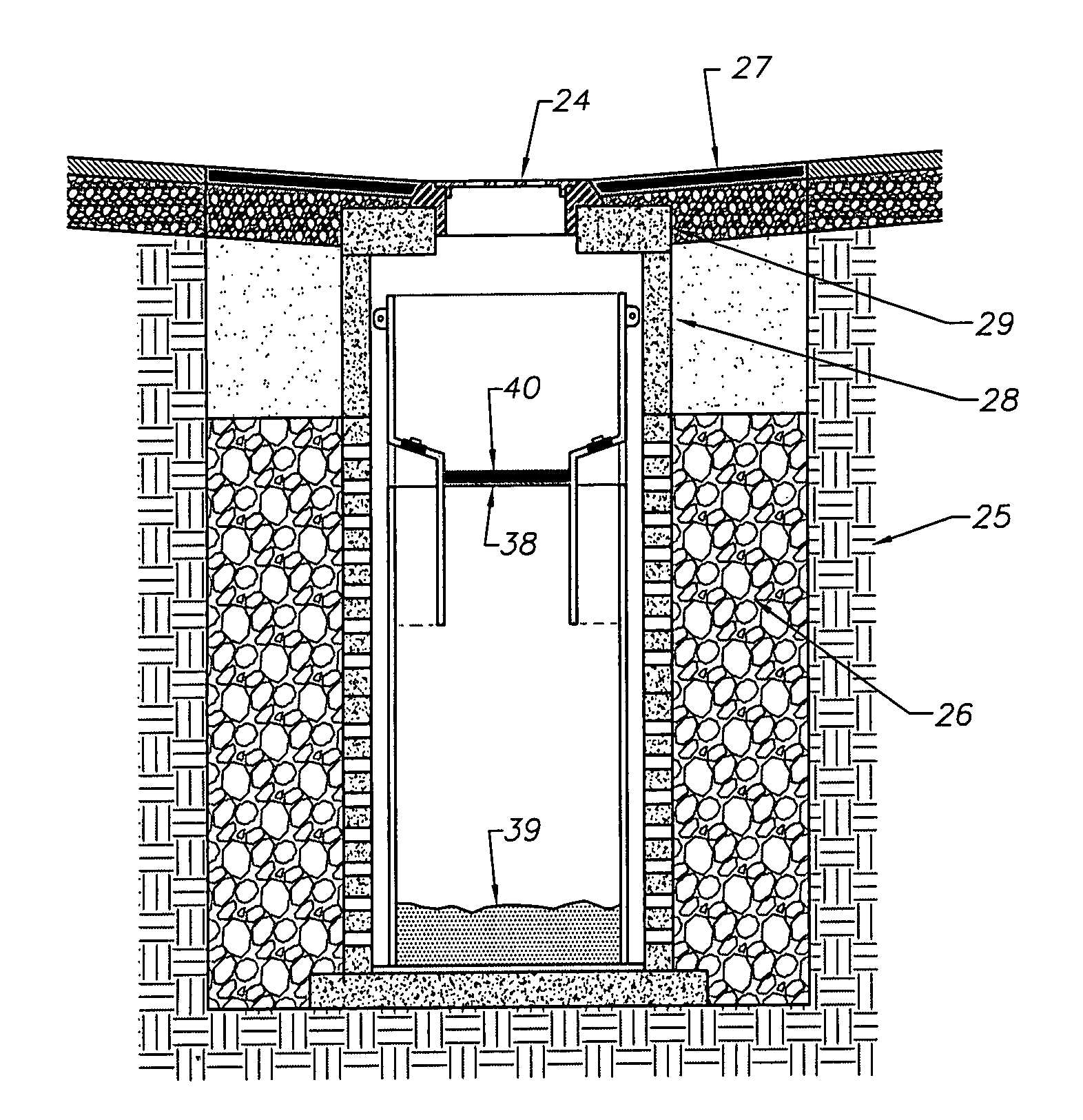
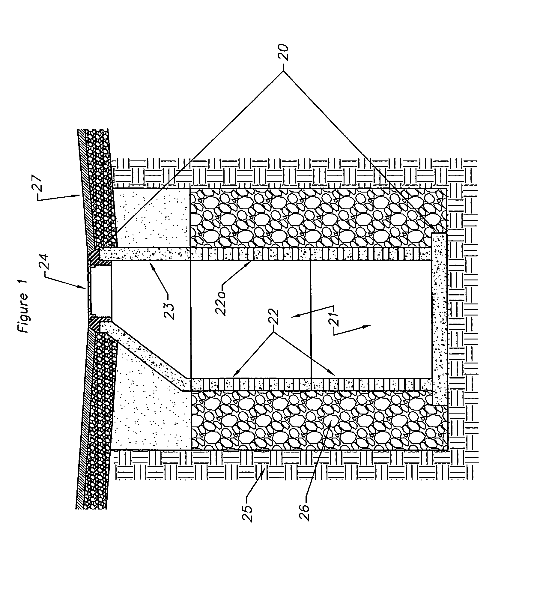
[0017]Referring more particularly to the drawings, FIG. 1 shows a typical drywell 20 of the type to which this invention could be applied. The drywell chamber 21 is constructed of a pair of stacked perforated precast concrete cylinders 22 topped with a precast concrete cone 23 and a grated steel lid 24. The precast concrete components have been placed in a hole excavated into the native soils 25 and backfilled with drain rock 26. The adjacent paved surfaces 27 are typically constructed such that they are sloped causing storm water to run toward or drain directly into the drywell 20 through the grated steel lid 24. Once storm water is collected into the drywell chamber 21 the water is discharged through the perforations 22a of the precast concrete cylinders 22. The storm water is then infiltrated through the drain rock 26 and into the native soils 25.

[0018]This particular invention is directed toward retrofitting previously constructed drywells of the type described above in order to...


PUM


Abstract

The present invention is a drywell retrofit sump insert designed to be placed inside an existing drywell or other similar Underground Injection Control (UIC). The drywell insert helps protect groundwater by removing pollutants from raw storm water runoff that enters the drywell before the drywell infiltrates the storm water into the ground. Once the raw storm water enters the drywell retrofit sump insert, sand, silt, grit, and other high-density pollutants settle out of the storm water stream and accumulate in the bottom of the drywell retrofit sump insert. Oil, grease, and other low-density pollutants float on top of the standing water inside the drywell retrofit sump insert and are kept inside by the oil baffles on the outlet holes. The drywell retrofit sump insert is comprised of a rigid cylinder with an integral flanged bottom attached by means of a watertight joint.

Description

CROSS REFERENCE TO RELATED APPLICATIONS[0001]61 / 462,245STATEMENT REGARDING FEDERALLY SPONSORED RESEARCH OR DEVELOPMENT[0002]NoneBACKGROUND OF THE INVENTION[0003]In many parts of the country, there are no municipal storm sewer systems to convey storm water from a developed property to natural water bodies such as rivers and lakes. In these areas without storm sewers, drywells are sometimes used for the localized disposal of collected storm water from public roadways and private properties. Typically, these drywells are constructed of various products and materials, but almost all employ some kind of perforated tank or chamber which is installed underground in an excavated hole and backfilled with rocks or clean gravel.[0004]The storm water from roof tops and paved areas is directed to the drywell through a grated opening at the pavement surface or via underground pipes. The storm water in the chamber then percolates through the perforations in the chamber, through the voids between t...

Claims


Application Information

Patent Timeline
Patent Type & Authority Applications(United States)
IPC IPC(8): E02B13/00
CPCE03F1/002B01D17/0208B01D17/00E03F5/0404Y02A10/30Y02A20/40
Inventor HARDGRAVE, GRANT MICHAEL
Owner HARDGRAVE GRANT MICHAEL
Why Eureka
Try Eureka