Manifold assembly for controlling gas flow and flow distribution in a fuel cell stack

a fuel cell and manifold technology, applied in the direction of fuel cell details, electrochemical generators, electrochemical generators, etc., can solve the problems of reducing the lifespan of the fuel cell stack, and the control of the fuel gas supply to individual fuel cells within the stack requires a complex piping and fuel delivery assembly, so as to reduce the amount increase the effect of inlet fuel flow

Active Publication Date: 2012-08-02
FUELCELL ENERGY INC
View PDF3 Cites 23 Cited by
  • Summary
  • Abstract
  • Description
  • Claims
  • Application Information

AI Technical Summary

Benefits of technology

[0011]In certain embodiments, the external manifold is an anode exhaust manifold for receiving anode exhaust gas from an anode outlet face of said fuel cell stack, and the enclosure of the manifold includes an opening adapted to face the anode outlet face of the fuel cell stack and through which anode exhaust gas is output from the anode outlet face into the enclosure when the manifold abuts the anode outlet face. In such embodiments, there is at least one exhaust outlet formed in the enclosure for outputting the anode exhaust gas from the manifold, and at least one baffle is disposed in the enclosure between the exhaust outlet and the opening in the enclosure so as to control the direction of the anode exhaust gas flow received from fuel cells closest to the exhaust outlet around the baffle. In some...

Problems solved by technology

This uneven gas distribution leads to a decreased fuel cell stack lifespan.
However, controlling of the f...

Method used


Image

  • Manifold assembly for controlling gas flow and flow distribution in a fuel cell stack
  • Manifold assembly for controlling gas flow and flow distribution in a fuel cell stack
  • Manifold assembly for controlling gas flow and flow distribution in a fuel cell stack

Examples


Embodiment Construction

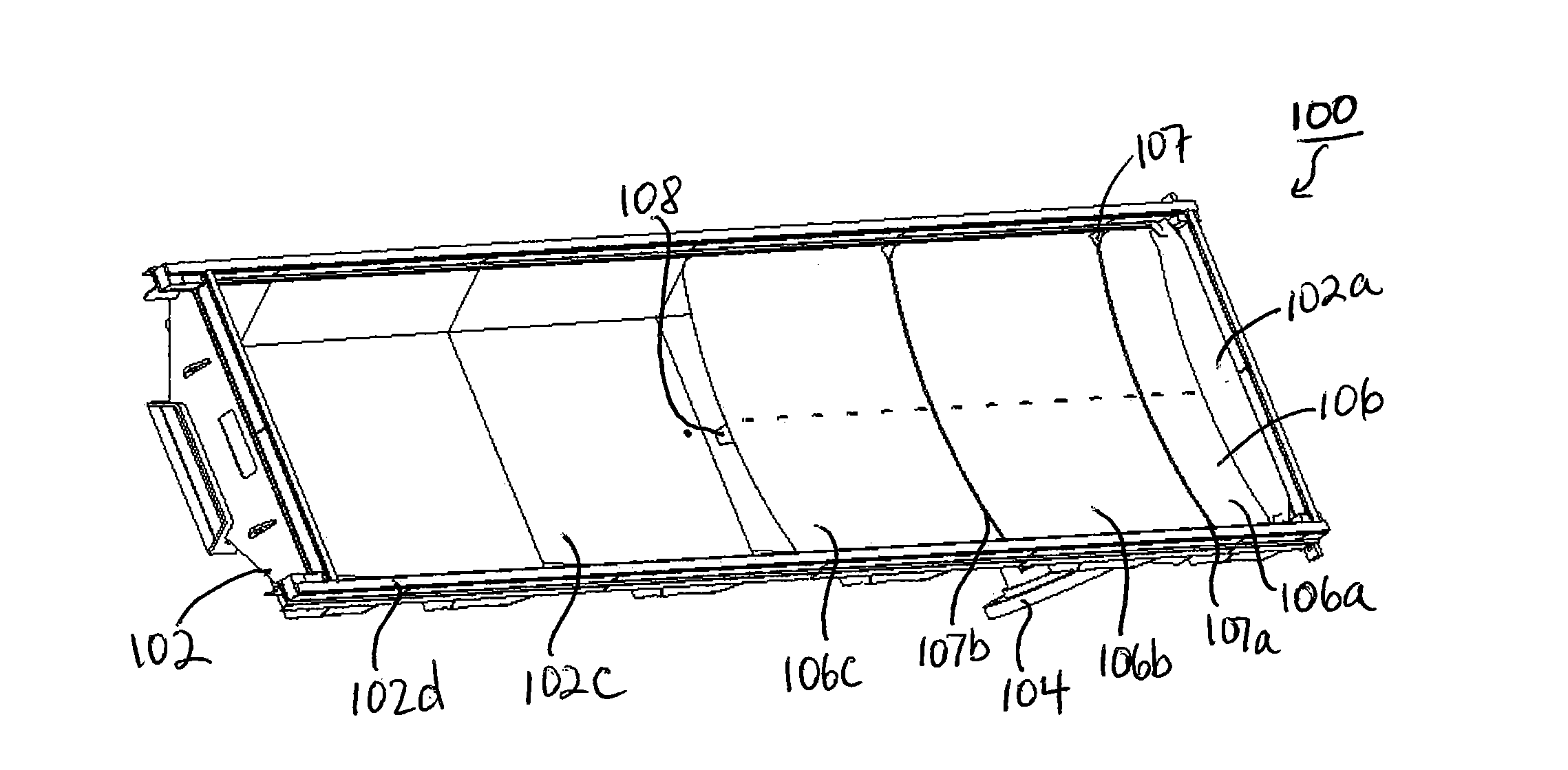
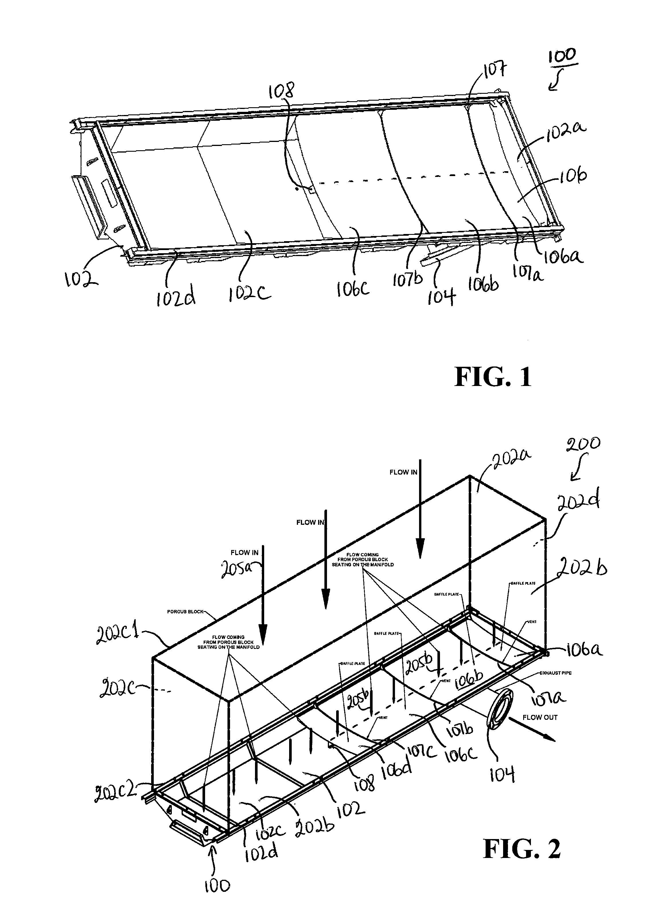
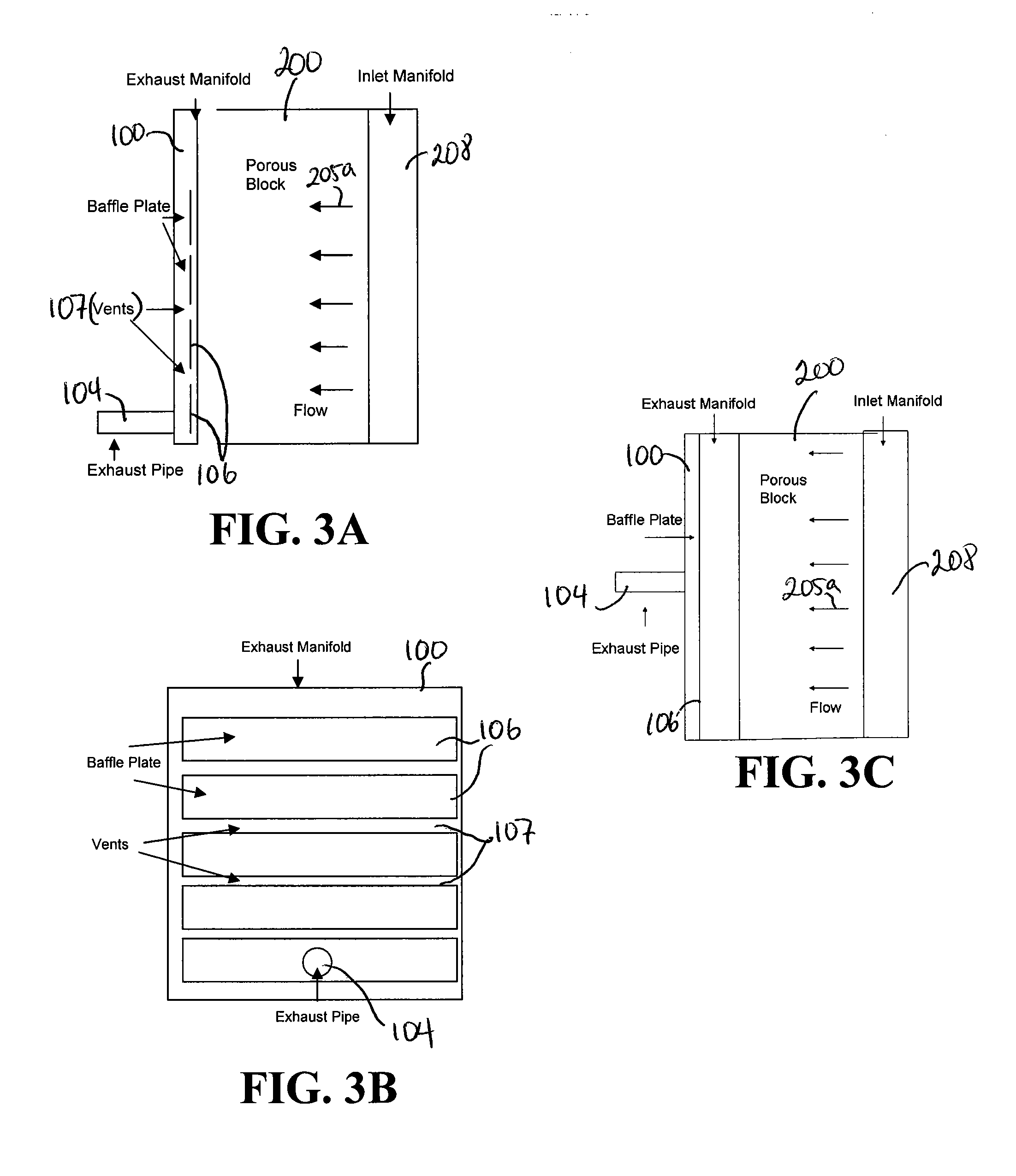
[0027]The present invention provides a manifold assembly for use in a fuel cell system which controls gas flow distribution through a fuel cell stack of the system so as to achieve more uniform gas flow distribution through each fuel cell in the stack and to provide cooling to desired areas of the stack, such as the anode inlet area of the stack. FIGS. 1-3C show illustrative embodiments of an anode manifold assembly 100 for use in the fuel cell system and for controlling the gas flow distribution through the fuel cell stack. The anode manifold assembly 100 shown in FIGS. 1-3C is used with, or as part of, a fuel cell stack that comprises a plurality of stacked fuel cells and, in some cases, hundreds of stacked fuel cells. The fuel cell stack includes anode inlet and outlet faces for receiving and outputting, respectively, fuel gas and anode exhaust, and cathode inlet and outlet faces for receiving and outputting, respectively, oxidant gas and cathode exhaust. Each of the cathode inle...


PUM


Abstract

A manifold assembly for use with a fuel cell stack for the purpose of ensuring a desired flow distribution to fuel cells within the stack, with the most commonly desired being uniform flow distribution. Said manifold assembly comprising: an external manifold for abutting and sealingly enclosing a face of the fuel cell stack, wherein the manifold comprises an enclosure for one of: providing inlet gas to the fuel cell stack and receiving exhaust gas from said fuel cell stack; and one or more baffles disposed in the enclosure of the external manifold, the one or more baffles one of: (a) controlling gas flow distribution and direction of the inlet gas from the enclosure to fuel cells of the fuel cell stack to achieve a predetermined distribution or a uniform distribution; and (b) controlling gas flow distribution of the exhaust gas flow within the enclosure to achieve the predetermined distribution or the uniform distribution of gas to fuel cells of the fuel cell stack. A multi-stack fuel cell system including a baffling assembly with one or more baffles for providing a predetermined gas flow distribution to each fuel cell stack in the fuel cell system is also described. The baffling assembly is provided at a system level and comprises one or more baffles in an intake assembly and/or in an exhaust assembly of the multi-stack fuel cell system, so that each fuel cell stack receives a predetermined amount of gas.

Description

FIELD OF THE INVENTION[0001]This invention relates to fuel cell systems with at least one fuel cell stack and an external manifold and, in particular, to a manifold assembly or a flow distribution control assembly for use in a fuel cell system having at least one externally manifolded fuel cell stack. More particularly, the invention comprises an assembly that includes one or more baffle plates disposed in one or more of the manifolds of the fuel cell stack for controlling the flow distribution of the gases among multiple fuel cells of the stack. Variations of the baffling principal can be applied at a system level to regulate gas flow to a fuel system that includes two or more fuel cell stacks. More particularly, the system level baffling assembly comprises one or more baffle plates in an intake assembly and / or in an exhaust assembly of the multiple fuel cell system so that each fuel cell stack in the system receives a predetermined amount of gas flow.BACKGROUND OF THE INVENTION[00...

Claims


Application Information

Patent Timeline
IPC IPC(8): H01M8/04
CPCH01M8/04082Y02E60/50H01M8/2485H01M8/2415H01M8/2484H01M8/0289H01M8/04276H01M8/04089
Inventor MCINERNEY, JOSEPH P.ERNST, JR., LOUIS F.FAROOQUE, MOHAMMADVENKATARAMAN, RAMAKRISHNANHANSELL, ERICNEDU, DANIELADAVIS, KEITHSNYDER, WILLIAMQUATANNENS, MICHAEL
Owner FUELCELL ENERGY INC
Why Eureka
Try Eureka