Ophthalmic surgical microscope

a surgical microscope and ophthalmology technology, applied in the field of ophthalmological surgical microscopes, can solve the problems of displacement of the inserting position of the iol, inability to correctly apply the marking, etc., and achieve the effect of high accuracy

Inactive Publication Date: 2012-08-02
NIDEK CO LTD
View PDF6 Cites 56 Cited by
  • Summary
  • Abstract
  • Description
  • Claims
  • Application Information

AI Technical Summary

Benefits of technology

[0012]The present invention has a purpose to provide an ophthalmic surgical microscope valuable in performing IOL surgery with high accuracy.

Problems solved by technology

However, there is a possibility that a posture of a patient is different between at the time of measuring a corneal shape and at the time of applying markings, and thus the marking could not be applied correctly in the position corresponding to the astigmatic axis.
This may cause displacement of an inserting position of the IOL.

Method used


Image

  • Ophthalmic surgical microscope
  • Ophthalmic surgical microscope
  • Ophthalmic surgical microscope

Examples


Embodiment Construction

[0019]In the following detailed description, for purpose of explanation, numerous specific details are set forth in order to provide a thorough understanding of the disclosed embodiments. It will be apparent, however, that one or more embodiments may be practiced without these specific details. In other instances, well-known structures and devices are schematically shown in order to simplify the drawing.

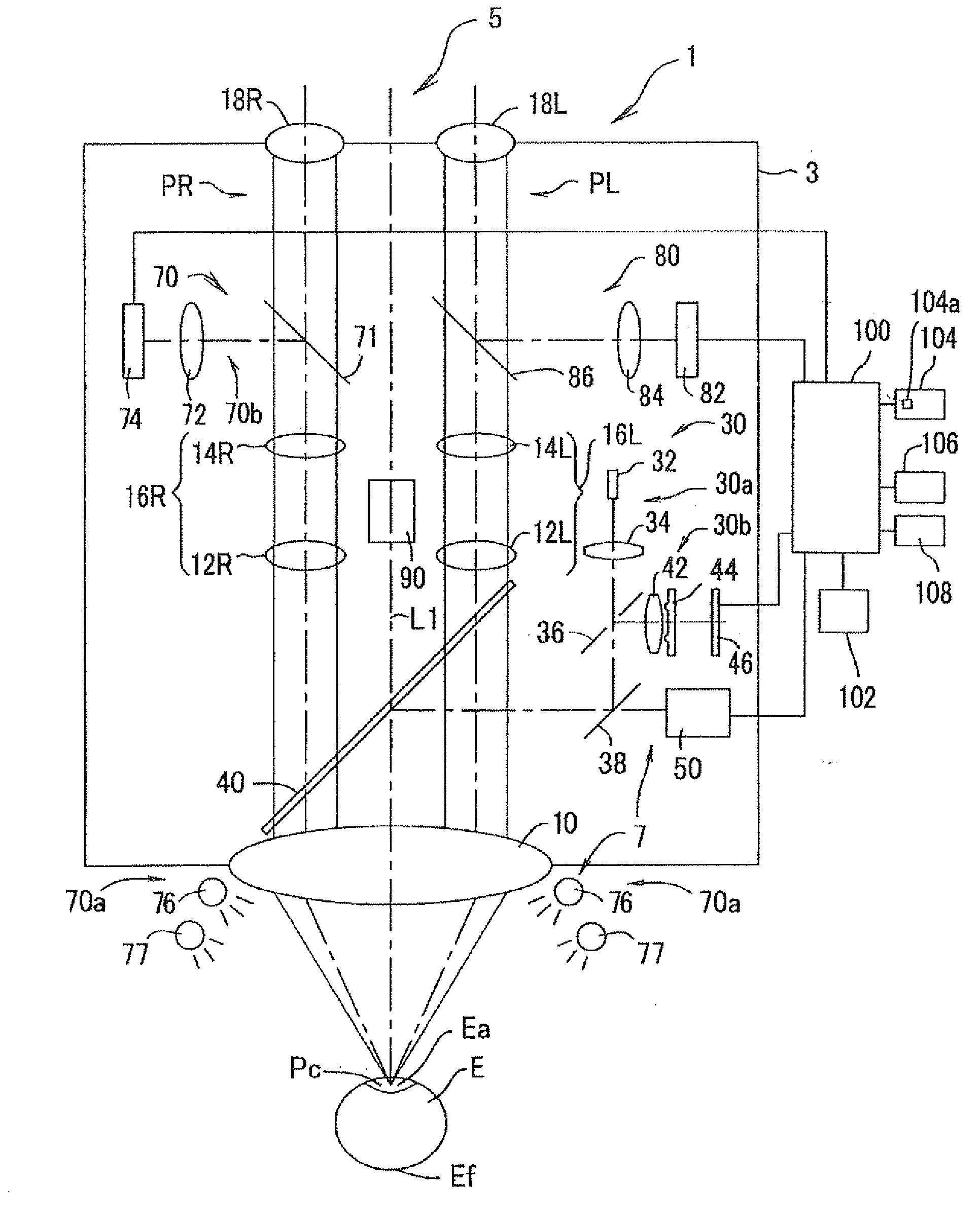
[0020]A preferred embodiment of the present invention will be described below referring to the accompanying drawings. FIG. 1 is a schematic diagram to explain a surgical microscope in the present embodiment. In this embodiment, an axial direction of a patient's eye (eye E) is referred to as a Z direction (in a vertical direction in FIG. 1), a horizontal direction (a right-to-left direction of the eye) is referred to as an X direction (in a lateral direction in FIG. 1), and a perpendicular direction is referred to as a Y direction (in a backward and forward direction relative to a dra...


PUM


Abstract

An ophthalmic surgical microscope comprises: an observation optical system for observing a patient's eye during surgery; a corneal shape measuring unit for measuring a corneal shape of the patient's eye placed in a surgical position; and a controller configured to output guide information for guiding a surgery with an intraocular lens based on a measurement result obtained by the corneal shape measuring unit to an output device.

Description

CROSS-REFERENCE TO RELATED APPLICATIONS[0001]This application is based upon and claims the benefit of priority from the prior Japanese Patent Application No. 2011-015779, filed Jan. 27, 2011, the entire contents of which are incorporated herein by reference.BACKGROUND[0002]1. Technical Field[0003]The present invention relates to an ophthalmic surgical microscope to be used in ophthalmic surgery.[0004]2. Related Art[0005]As one of intraocular lenses (IOL), recently, a TORIC-IOL designed to correct astigmatism appears on the market. In this case, a surgeon or operator measures an astigmatic axis of a patient's eye (to be operated on) in advance by use of a corneal shape measuring device (see Patent Document 1). The surgeon then applies a first marking in a horizontal axis of the patient's eye by using a special-purpose member and further applies a second marking at a position corresponding to an astigmatic axis of the eye with reference to the first marking, and he / she inserts an IOL ...

Claims


Application Information

Patent Timeline
Patent Type & Authority Applications(United States)
IPC IPC(8): A61F9/007A61B3/16A61B6/02A61B6/00
CPCA61B3/132A61B3/13A61F2/16A61B3/135A61B3/16A61B3/107A61B3/103G02B21/0012G02B21/06G02B21/20A61F2/142
Inventor HANEBUCHI, MASAAKITAKII, MICHIHIROENDO, MASAKAZUSUNADA, TSUTOMU
Owner NIDEK CO LTD
Why Eureka
Try Eureka