Safety controller and safety control method

Inactive Publication Date: 2012-08-02
TOYOTA JIDOSHA KK
View PDF3 Cites 19 Cited by
  • Summary
  • Abstract
  • Description
  • Claims
  • Application Information

AI Technical Summary

Benefits of technology

[0017]According to the above aspects of the present invention, it is possible to provide a safety controller and a safety control method which are capable of p

Problems solved by technology

This causes a problem of an incre

Method used


Image

  • Safety controller and safety control method
  • Safety controller and safety control method
  • Safety controller and safety control method

Examples


Example

First Embodiment of the Invention

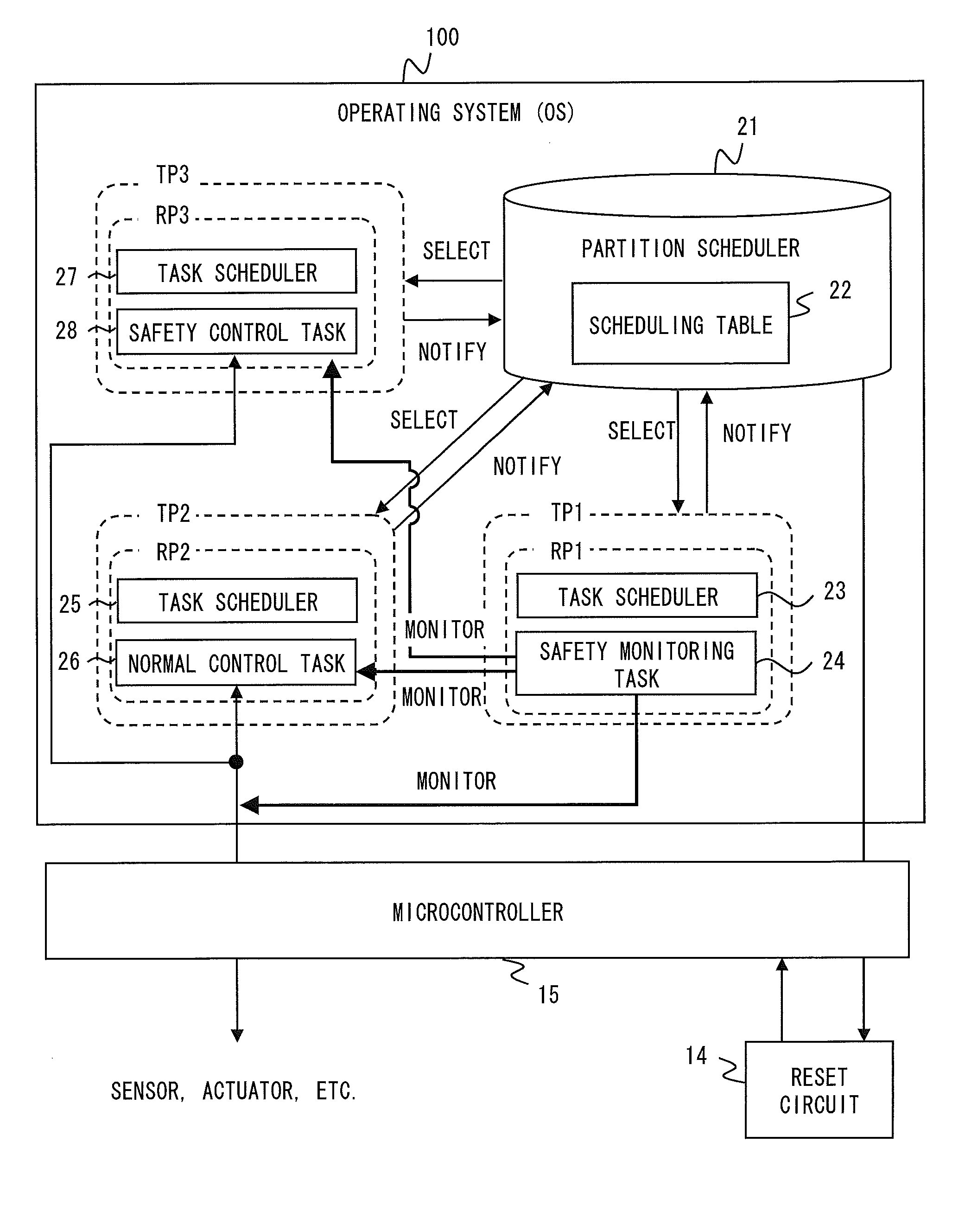
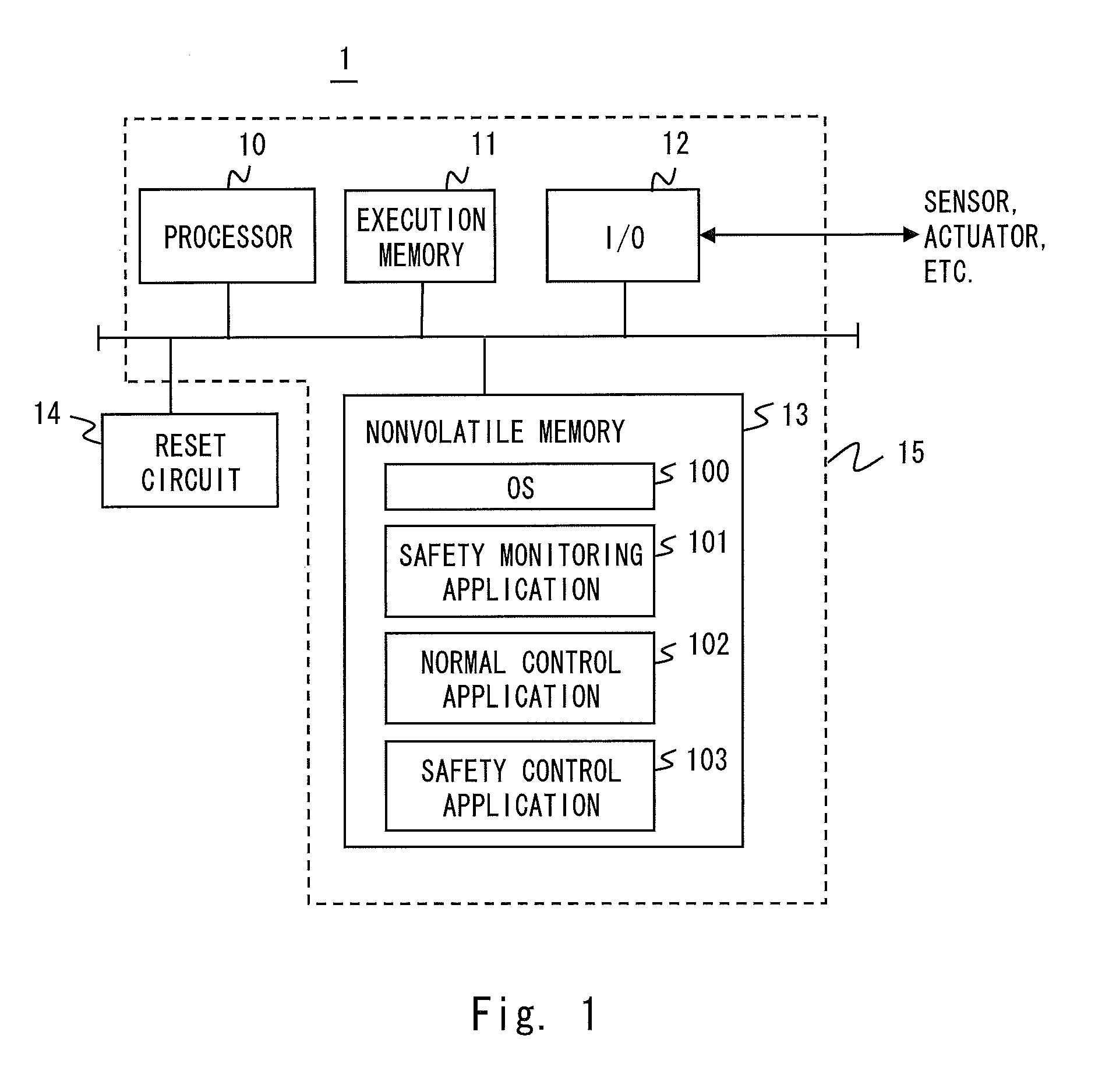
[0038]A safety controller 1 according to this embodiment is mounted in a service robot, transportation equipment, or the like and executes safety control for ensuring functional safety. The safety controller 1 is adapted to execute a safety-related application and a non-safety-related application in one computer system. FIG. 1 is a block diagram showing a configuration example of the safety controller 1 according to this embodiment.

[0039]A processor 10 fetches programs (instruction stream), decodes instructions, and carries out arithmetic processing according to the result of instruction decoding. Though only one processor 10 is illustrated in FIG. 1, the safety controller 1 may have a multiprocessor configuration including a plurality of processors 10. The processor 10 may be a multicore processor. The processor 10 executes an operating system (OS) 100 as a system program to thereby provide a multiprogramming environment. The multiprogramming enviro...

Example

Second Embodiment of the Invention

[0102]Referring now to FIG. 9, a safety controller 2 according to a second embodiment of the invention will be described. FIG. 9 is a block diagram showing a configuration example of the safety controller 2 according to the second embodiment. Hereinafter, description of the same contents as those of the safety controller 1 according to the first embodiment is omitted.

[0103]The processor 10 detects an interrupt from a control target, and a timer interrupt. The processor 10 detects an interrupt from a control target upon receiving an interrupt signal from the control target. The processor 10 executes an interrupt handler 31, which will be described later, upon detecting the interrupt from the control target. Here, the microcontroller 15 of the safety controller 2 includes a timer (not shown). The timer outputs an interrupt signal to the processor 10 in a predetermined period based on a clock signal. The processor 10 detects the timer interrupt upon re...

Example

Third Embodiment of the Invention

[0138]Subsequently, the safety controller 2 according to a third embodiment of the invention will be described. Note that the configuration of the safety controller 2 according to the third embodiment is similar to that of the safety controller 2 according to the second embodiment, so the description thereof is omitted. The relationships between the partition scheduler 21, the tasks 24, 26, 28, and 30, and the interrupt handler 31 are also similar to those of the safety controller 2 according to the second embodiment, so the description thereof is omitted.

[0139]Referring now to FIG. 16, the scheduling procedure according to the second embodiment of the present invention will be described. FIG. 16 is a flowchart showing a specific example of the scheduling procedure according to the second embodiment of the present invention. Note that steps S101 to S105 are similar to steps S91 to 95, so the description thereof is omitted. Note that TPX in FIG. 16 in...


PUM


Abstract

The present invention relates to time partitioning to prevent a failure of processing while suppressing execution delay of interrupt processing even when the interrupt processing is executed. A safety controller includes: a processor; a system program for controlling allocation of an execution time of the processor to a safety-related task, a non-safety-related task, and an interrupt processing task; and an interrupt handler. Upon generation of an interrupt, the processor executes the interrupt handler to reserve execution of the interrupt processing task as an execution reserved task, and executes the system program to schedule the tasks in accordance with scheduling information on a safety-related TP to which the safety-related task belongs, a non-safety-related TP to which the non-safety-related task belongs, and a reservation execution TP to which the execution reserved task belongs. When execution of a task in a previous TP is finished before the period of the previous TP prior to the execution reservation TP has expired, the execution time in the previous TP is allocated to the execution reserved task.

Description

TECHNICAL FIELD[0001]The present invention relates to a safety controller mounted in a service robot, transportation equipment, and the like to ensure functional safety, and particularly to a safety controller using a computer system.BACKGROUND ART[0002]Service robots are required to ensure functional safety by constantly monitoring a safety state using an external sensor and a self-diagnosis device and by executing appropriate safety control logic upon detecting some risk.[0003]IEC 61508 has been established as an international standard for functional safety of the service robots described above as well as systems which operate on an electrical principle, such as transportation equipment. In IEC 61508, a system provided to ensure functional safety is called a safety-related system. IEC 61508 defines various techniques for constructing the safety-related system using hardware, such as a microprocessor and a PLC (Programmable Logic Controller), and a computer program (software). The ...

Claims


Application Information

Patent Timeline
IPC IPC(8): G06F9/46G06F9/48
CPCG05B9/02G05B19/0426G05B19/0428G05B2219/34382G06F9/5077G05B2219/25343G05B2219/25347G06F9/4812G06F9/4887G05B2219/34383
Inventor TAIRA, TETSUYABITOH, HIROSHI
Owner TOYOTA JIDOSHA KK
Why Eureka
Try Eureka