Apparatus and method for gas-liquid separation

a technology of apparatus and gas liquid, which is applied in the direction of separation process, liquid degasification, and wellbore/well accessories, etc., can solve the problems of blowout, prior act separators, including mud-gas separators, cannot keep up with the flow rate of wellbore, etc., to improve separation efficiency, improve separation efficiency, and improve separation efficiency

Active Publication Date: 2012-08-09
HAVEN TECH SOLUTIONS LLC
View PDF4 Cites 14 Cited by
  • Summary
  • Abstract
  • Description
  • Claims
  • Application Information

AI Technical Summary

Benefits of technology

[0006]This invention relates to directionally shaping two-phase mixed flow in a curved path within a flow shaping line prior to introduction into a separator so as to enhance operation of the separator. Shaping the two-phase flow in a curvilinear path will allow centrifugal force to more readily force the heavier, denser liquid to the outside wall of the flow shaping line in the curved path and allow the lighter, less dense vapor or gas to occupy the inner wall of the flow shaping line. Once the gas is fairly well positioned on the inner wall of the flow shaping line, an exit port located on the inner wall will allow for the majority, if not all, of the gas, along with a low amount of liquid, to be sent to a conventional separator. A very high ratio of vapor / liquid at a flow rate much lower than the total flow rate within the flow shaping line is then sent to the conventional separator. This allows for efficient separation of the vapor from the liquid with the use of a smaller, more economical conventional separator than what would have been required for the full flow rate.
[0007]Additionally, a fluid guiding surface may be placed on the inner wall of the flow shaping line at the exit port to further aid in directing the gas to flow to the conventional separator. Furthermore, the liquid return from the conventional separator may be arranged in close downstream proximity to the exit port on the inner wall of the flow shaping line. The close proximity of the liquid return and the exit port allows the use of a venturi, nozzle or other restriction located adjacent the liquid return in the flow shaping line just downstream of the exit port. The venturi, nozzle or other restriction accelerates the velocity of the liquid in flow shaping line as it flows across the exit port. This acceleration of the liquid helps to pull the liquid out of the conventional gas-liquid separator. In addition, the acceleration of the liquid within the flow shaping line helps to prevent any solids that may be present in the gas-liquid flow from entering the exit port and it helps to lower the amount of liquid that enters the exit port and thus enters the conventional separator.
[0008]The invention therefore allows a gas-liquid fluid to be effectively separated with the use of a smaller conventional separator than was previously possible. The invention accomplishes this without using additional complex mechanical devices and thus will operate efficiently and reliably.

Problems solved by technology

If a kick is not quickly controlled, it can lead to a blow out.
Often times, however, prior act separators, including mud-gas separators, cannot keep up with the flow rate from the wellbore.

Method used


Image

  • Apparatus and method for gas-liquid separation
  • Apparatus and method for gas-liquid separation
  • Apparatus and method for gas-liquid separation

Examples


Embodiment Construction

[0020]In the detailed description of the invention, like numerals are employed to designate like parts throughout. Various items of equipment, such as pipes, valves, pumps, fasteners, fittings, etc., may be omitted to simplify the description. However, those skilled in the art will realize that such conventional equipment can be employed as desired.

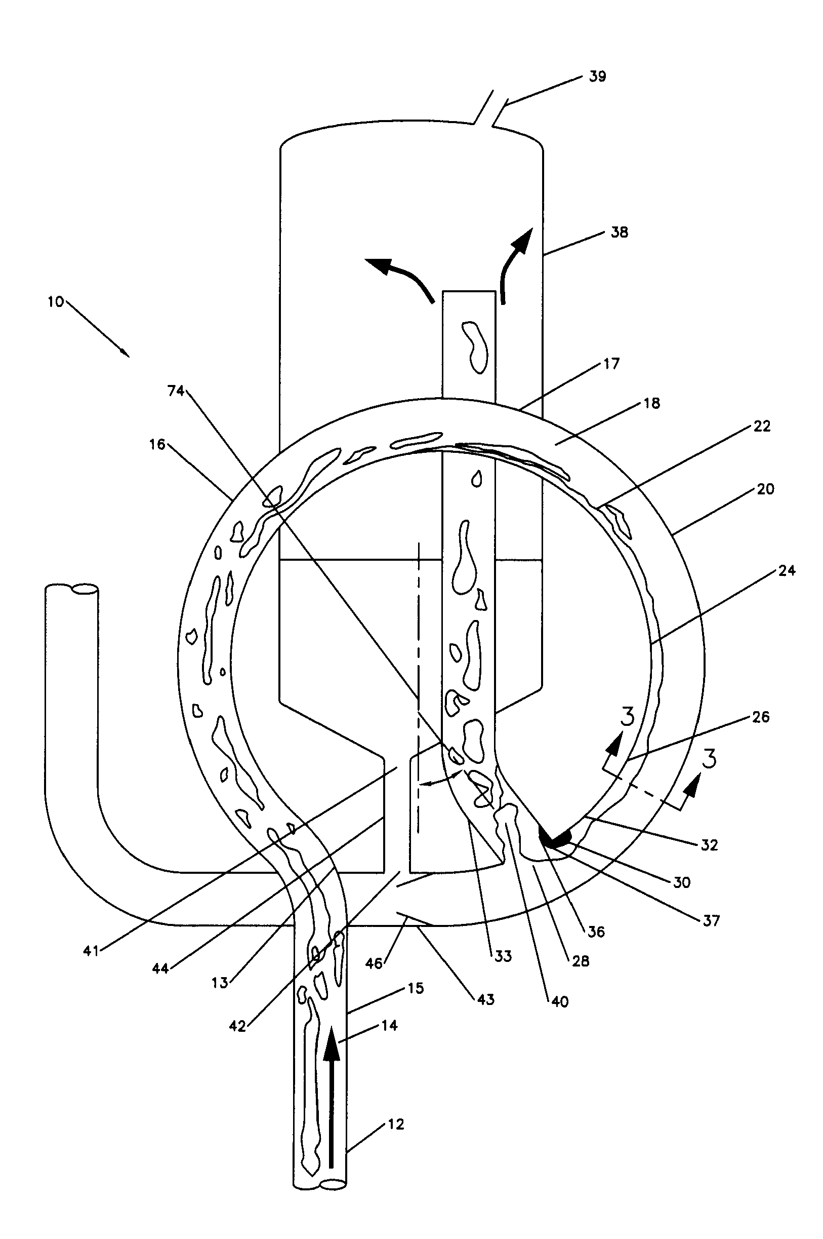
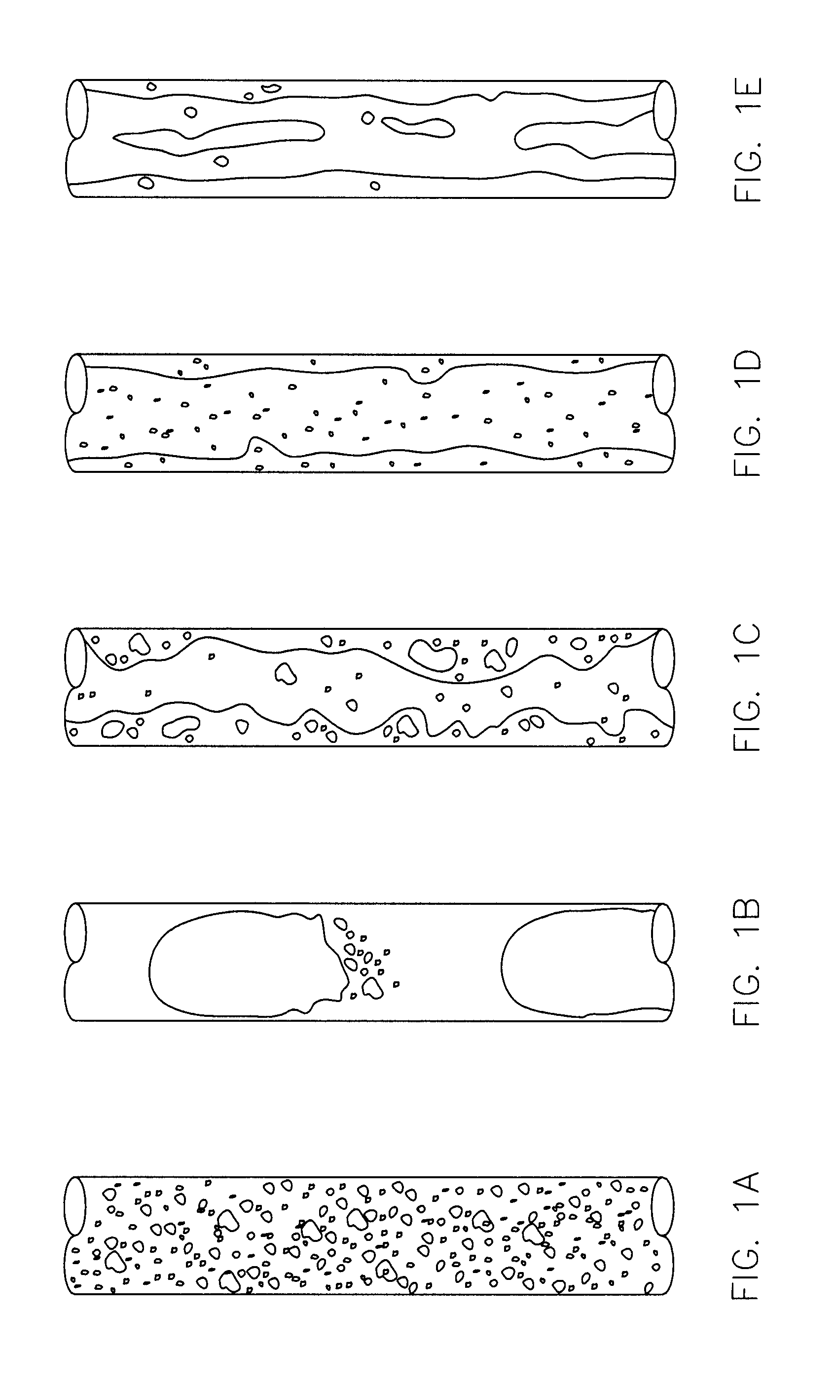
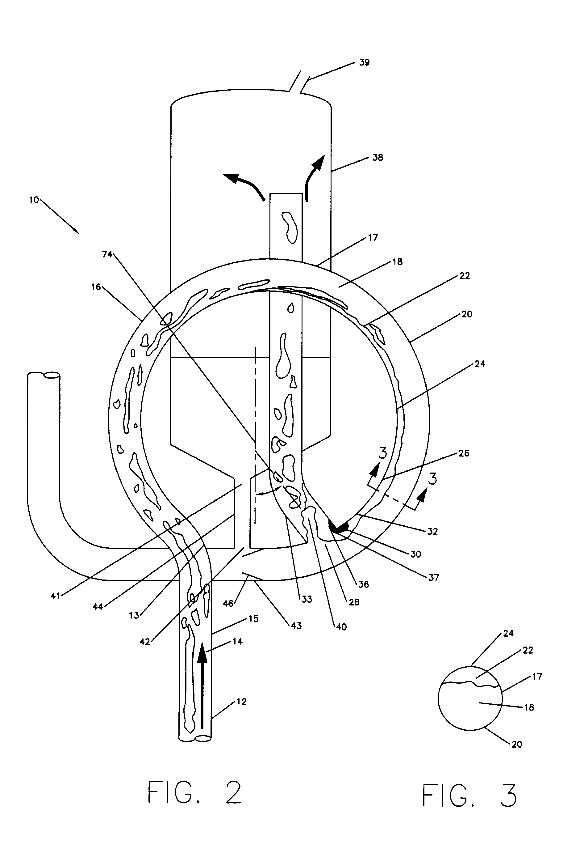
[0021]FIG. 2 illustrates a cross-sectional view of an embodiment of a separation apparatus 10. In an exemplary embodiment, the separation apparatus 10 includes a gas-liquid flow 12 traveling in a vertical direction 14 in a main line 15. The gas-liquid flow 12 could be any type of multiphase gas-liquid flow regime or flow pattern, such as, for example, bubble flow, slug or plug flow, churn flow, annular flow or wispy annular flow. The gas-liquid flow 12 within main line 15 is directed into a circular flow path 16 in a flow shaping line 17. The circular flow path 16 of flow shaping line 17 creates an increased distribution of the gas on inn...


PUM

PropertyMeasurementUnit
shapeaaaaaaaaaa
radiusaaaaaaaaaa
velocityaaaaaaaaaa

Abstract

A two phase gas-liquid separation apparatus is provided that shapes the flow in a flow shaping line. Shaping the two-phase flow allows centrifugal force to send the heavier, denser liquid to the outside wall of the flow shaping line and allows the lighter, less dense vapor or gas to occupy the inner wall of the flow shaping line. With the gas positioned on the inner wall of the flow shaping line, an exit port on the inner wall will allow for the majority, if not all, of the gas, along with a low amount of liquid, to be sent to a conventional separator. A high ratio of vapor/liquid at a flow rate much lower than the total flow rate within the flow shaping line is sent to the conventional separator. This allows for efficient separation of the vapor from the liquid with the use of a smaller conventional separator.

Description

FIELD OF THE INVENTION[0001]The present invention generally relates to the separation of gas from a gas-liquid two phase flow stream. More specifically, it relates to directionally shaping the gas-liquid two phase flow stream so that the majority of the gas is located in a certain area of the flow stream, which allows effective separation of the gas and the liquid.BACKGROUND OF THE INVENTION[0002]A gas-liquid two phase flow stream includes a mixture of different fluids having different phases, such as air and water, steam and water, or oil and natural gas. A gas-liquid two phase flow takes many different forms and may be classified into various types of gas distribution within the liquid. These classifications are commonly called flow regimes or flow patterns and are illustrated in FIGS. 1A-1E. Bubble flow as illustrated in FIG. 1A is typically a continuous distribution of liquid with a fairly even dispersion of bubbles in the liquid. Slug or plug flow as illustrated in FIG. 1B is a...

Claims


Application Information

Patent Timeline
Patent Type & Authority Applications(United States)
IPC IPC(8): B01D19/00
CPCB01D19/0057E21B43/36E21B43/34
Inventor ELMS, DAVID JAMESHUDSPETH, GREG ALLEN
Owner HAVEN TECH SOLUTIONS LLC
Why Eureka
Try Eureka