Hydraulic shock absorber and damping force generator

Inactive Publication Date: 2012-08-09
SHOWA CORP
View PDF4 Cites 2 Cited by
  • Summary
  • Abstract
  • Description
  • Claims
  • Application Information

AI Technical Summary

Benefits of technology

[0018]According to the present invention, it is possible to reduce the number of components and

Problems solved by technology

However, simply omitting the valve stopper and the valve sheet may result in deformation of this valve because an industrial tool for rotating and tightening the nut hits a valve for damping when the valve device is assembled.
However, usage of the flange nut makes the valve for generating damping for

Method used


Image

  • Hydraulic shock absorber and damping force generator
  • Hydraulic shock absorber and damping force generator
  • Hydraulic shock absorber and damping force generator

Examples


Embodiment Construction

[0034]Hereinafter, an exemplary embodiment of the present invention will be described in detail with reference to the attached drawings.

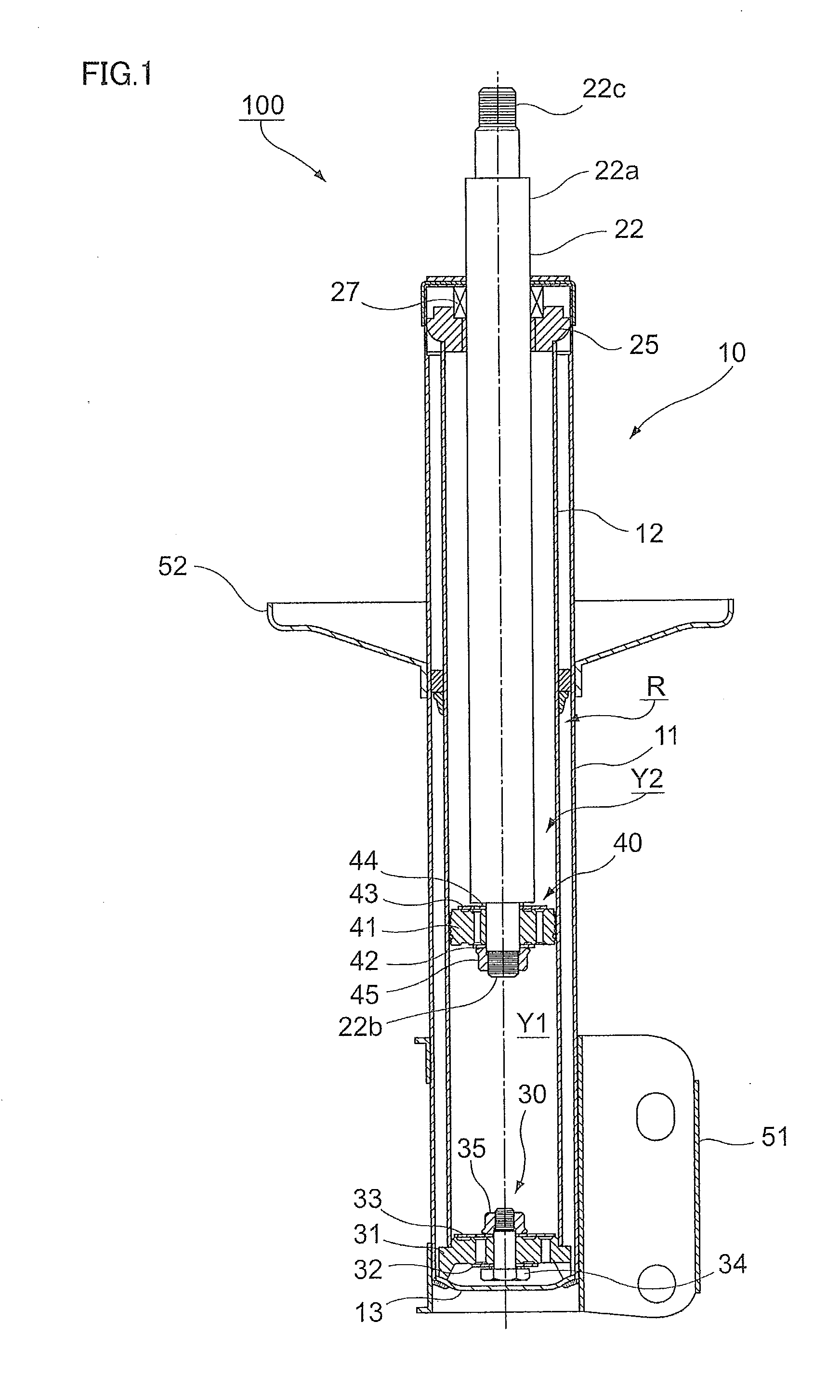
[0035]FIG. 1 is a view for illustrating a schematic configuration of a hydraulic shock absorber 100 according to the exemplary embodiment.

[0036]The hydraulic shock absorber 100 according to the exemplary embodiment is a multi-cylinder hydraulic shock absorber configuring a part of a strut-type suspension.

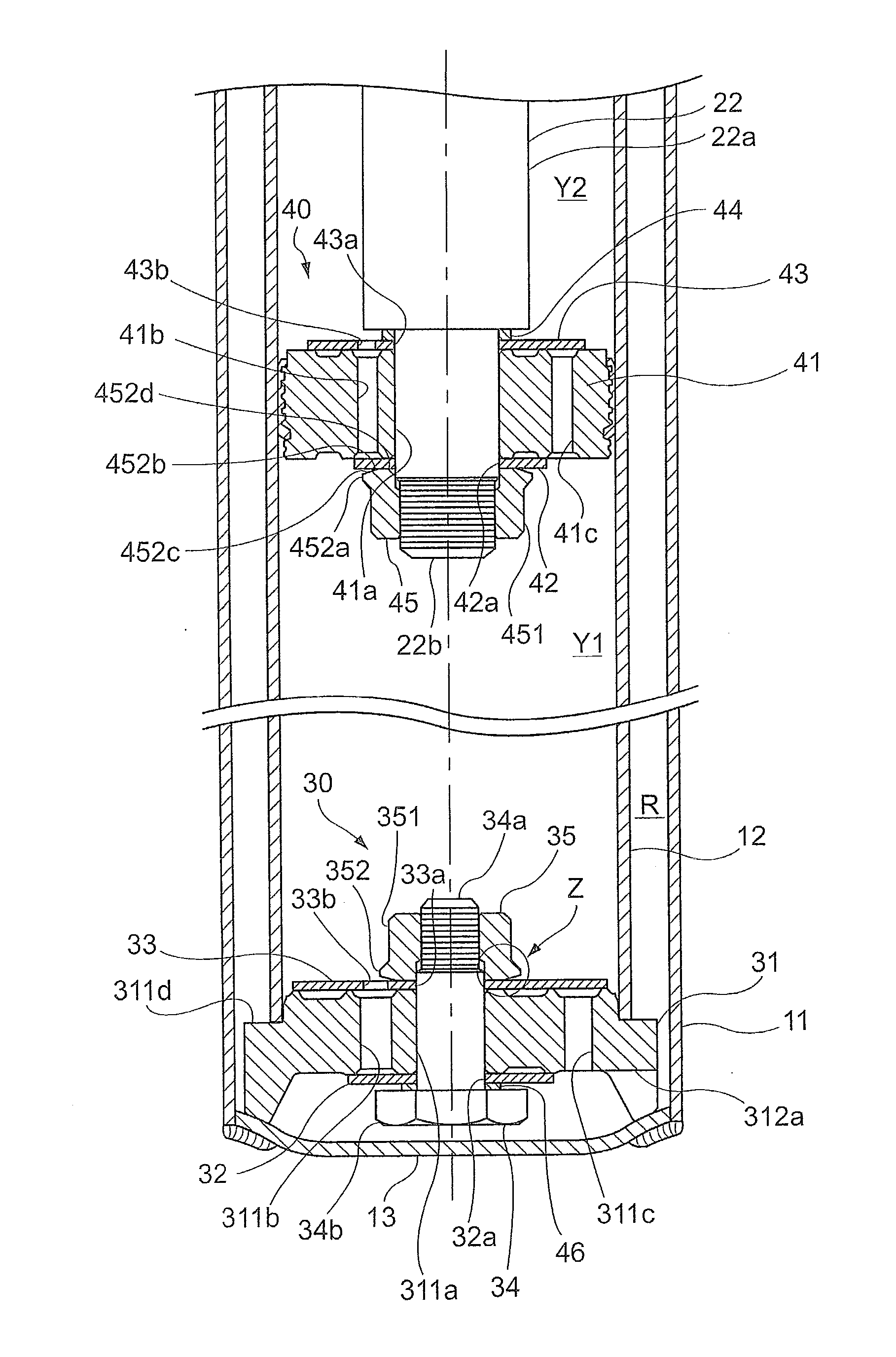
[0037]As shown in FIG. 1, the hydraulic shock absorber 100 is provided with a cylinder 10 including: an outer cylinder 11 that is formed into a cylinder having a thin wall thickness; an inner cylinder 12 that is contained in the outer cylinder 11 and is formed into a cylinder having a thin wall thickness; and a bottom cap 13 that covers one end of the outer cylinder 11 in a centerline direction of the cylinder (up-and-down direction in FIG. 1). Hereinafter, the centerline direction of the cylinder forming the outer cylinder 11 is simply referred to ...


PUM


Abstract

A hydraulic shock absorber includes: a dividing member dividing a closed space and having a communicating passage for communicating divided spaces; a valve covering an open end of the communicating passage; a bolt penetrating through the dividing member and the valve; and a nut fastening the dividing member and the valve together with the bolt. The bolt or the nut has a head fitted with an industrial tool, and a base end arranged on a valve side beyond the head to contact with the valve and including an extending part extending outside an outer shape of the head in a radial direction, a facing part of the base end facing the valve comes into contact with the valve at a position inside an outermost end of the extending part in the radial direction, and an outer region outside a contact part does not come into contact with the valve.

Description

CROSS REFERENCE TO RELATED APPLICATIONS[0001]This application is based on and claims priority under 35 USC §119 from Japanese Patent Application No. 2011-025756 filed Feb. 9, 2011.BACKGROUND[0002]1. Technical Field[0003]The present invention relates to a hydraulic shock absorber and a damping force generator.[0004]2. Related Art[0005]A suspension of a vehicle such as an automobile is provided with a hydraulic shock absorber using a damping force generator in order to appropriately absorb vibration transmitted from a road surface to the vehicle while moving and to improve ride quality and handling.[0006]For example, a hydraulic shock absorber described in Japanese Patent Application Laid Open Publication No. 2002-227900 has a following configuration. That is, the hydraulic shock absorber includes: a piston valve device that is configured by a cylinder formed of an inner cylinder in which a piston slide and an outer cylinder arranged outside the inner cylinder, as a double cylinder, a...

Claims


Application Information

Patent Timeline
IPC IPC(8): F16F9/16
CPCF16F9/3485
Inventor OSHIE, YUKIMATSUTAKE, YASUNORIKANEKO, KENICHIRO
Owner SHOWA CORP
Why Eureka
Try Eureka