
Soft pipe connecting device

a technology of connecting device and soft pipe, which is applied in the direction of hose connection, fluid pressure sealing joint, sleeve/socket joint, etc., can solve the problems of gas or liquid leakage, relatively complex form, and easy leakage of gas or liquor, and achieve the effect of convenient operation

Inactive Publication Date: 2012-08-09
LIANG GUANGREN
View PDF2 Cites 7 Cited by
  • Summary
  • Abstract
  • Description
  • Claims
  • Application Information

AI Technical Summary

Benefits of technology

[0003]In order to overcome the disadvantages of the prior art, the present invention provides a soft pipe connecting device that is connection closely, sealing well, easy to operate.
[0006]the groove may be provided therein with a sealing ring to enhance the seal of the soft pipe and the joint;
[0011]When used, the outer ring is sleeved on the soft pipe, the soft pipe is sheathed on the joint, and then through the external mechanical force, the outer ring is pulled to the direction of the joint, the outer ring radial expands deformation by the external force, extrudes and crosses the pawls of the joint, until the projection of the outer ring falls into the groove of the joint, at the same time, the pawls of the joint and the pawls of the outer ring are engaged mutually, clamps in the concave ring of the soft pipe to prevent the soft pipe fall from the joint effectively. In order to enhance the sealing effect between the joint and the soft pipe, the groove has the sealing ring. The limit baffle of the joint can effectively prevent the joint and the soft pipe slide to the limit baffle direction, generate gap.
[0012]Through the above structure design, the connected tightness between the thin-walled soft pipe and the joint are improved, sealing better, effectively preventing the leakage of gas and liquid, moreover, simple and convenient for installation, more practical.

Problems solved by technology

However, for the valid time of glue and the possibility of crevice, the former manner is, relatively complex and prone to gas or liquor leakage.
And the later manner can be limited that, when the wall of soft pipe is thin such as below 0.16 CM, its shape will change little under the pressure of clip which situation may causes the leakage of gas or liquid.
It might be worse when the connection position between soft pipe and joint is short and narrow.

Method used

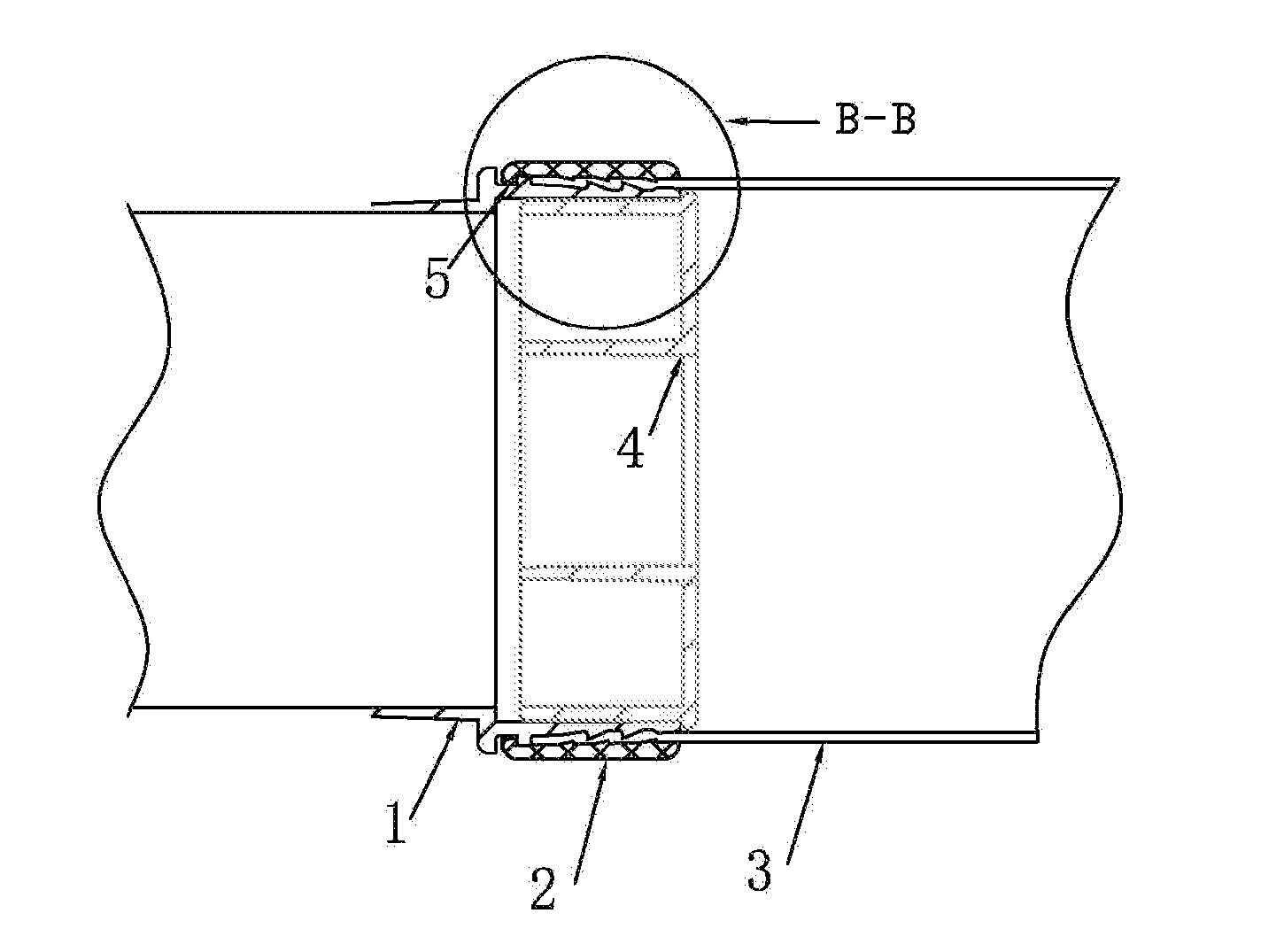

Image

  • Soft pipe connecting device
  • Soft pipe connecting device
  • Soft pipe connecting device

Examples


first embodiment

The First Embodiment

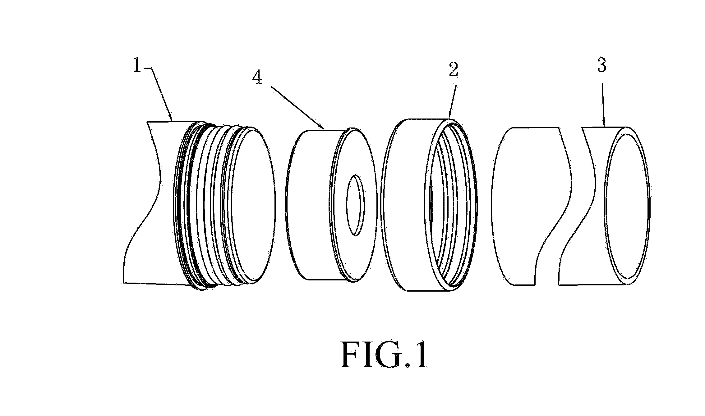
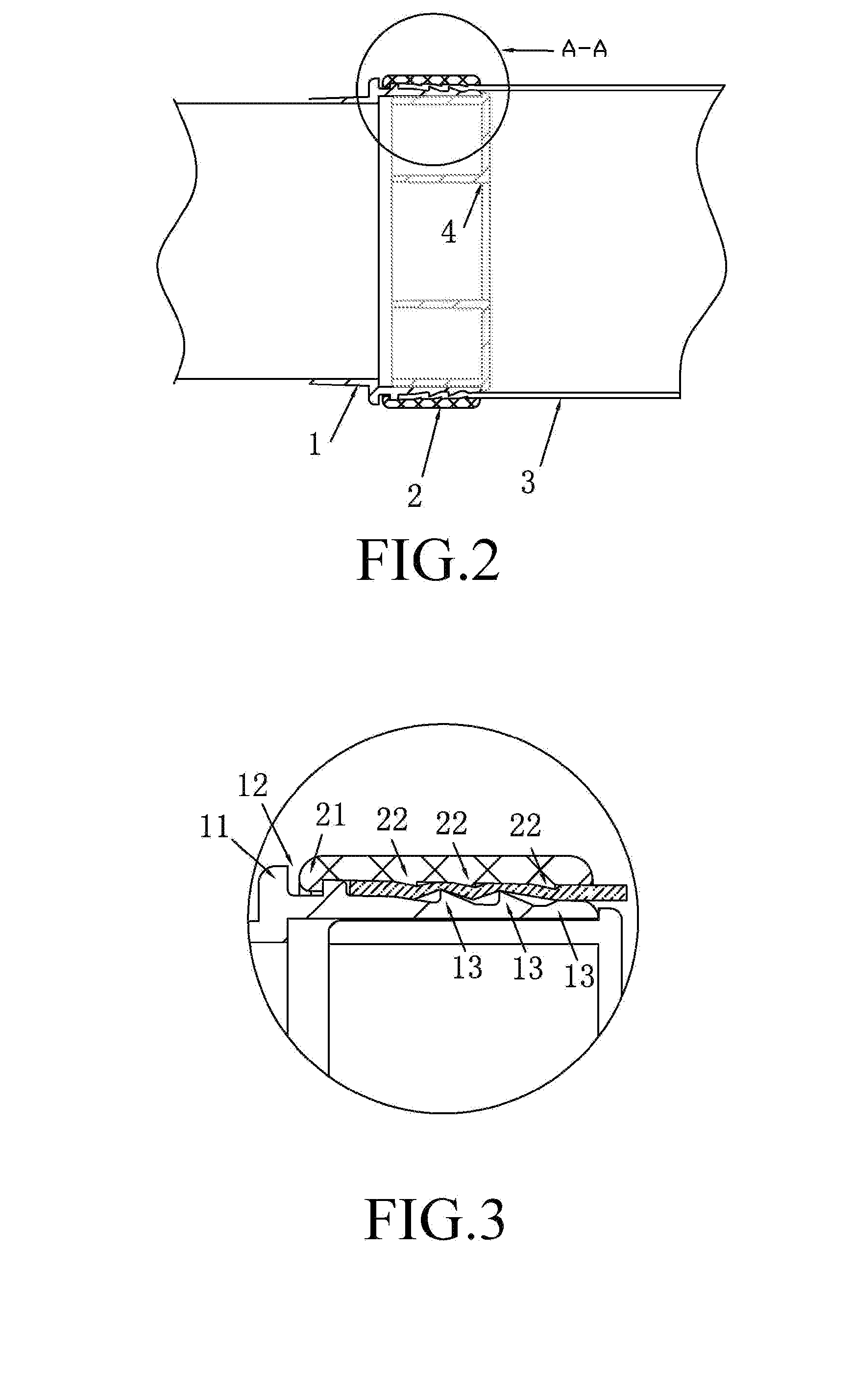
[0020]Referring to FIGS. 1-3, the first embodiment of the soft pipe connecting device, comprises a cylindrical joint 1, an outer ring 2, and a fixed sleeve 4. The fixed sleeve 4 is inside the joint 1 for supporting the joint 1, when the outer ring 2 that is sheathed on the joint 1 generates of radial pressure to the joint 1 to prevent the joint 1 radial deformation. The outside wall surface of the cylindrical joint 1 is provided in sequence with a limit baffle 11, a groove 12. and two pawls 13 whose tooth-tips are oriented towards the groove 12. The outer ring 2 is made of expandable material, such as plastic or metal, the embodiment is preferable to nylon, the inside wall surface of the outer ring 2 is provided with a projection 21 on the position corresponding to that of the groove 12 of the joint 1, and two reverse pawls 22 whose positions correspond to the two pawls 13 of the joint 1. Under the normal state, the diameter of the outer ring 2 is less than the d...

second embodiment

The Second Embodiment

[0022]Referring to FIGS. 4-6, the structure of the second embodiment and the first embodiment are basically the same. On the basis of the first embodiment, adding the sealing ring 5, which is in the groove 12 of the joint 1, can enhance the connection sealing effect between the soft pipe 3 and the joint 1.


PUM


Abstract

A soft pipe connecting device, comprising: a cylindrical joint, a fixed sleeve inside the joint for supporting the joint, and an outer ring sheathed outside the soft pipe and tightly pressing the soft pipe against the outer wall surface of the joint. The outside wall surface of the cylindrical joint is provided in sequence with a limit baffle, a groove and plurality of pawls whose tooth-tips are oriented towards the groove. The outer ring is made of expandable material. The inside wall surface of the outer ring is provided with a projection on the position corresponding to that of the groove of the joint, and plurality of reverse pawls whose positions correspond to those of the pawls of the joint. The groove may be provided therein with a sealing ring. The sealing effect is very good and can effectively prevent the leakage of gas or liquid.

Description

FIELD OF THE INVENTION[0001]The present invention relates to a connecting device, and more specifically to a connecting device connected to the soft pipes or soft pipe and rigid pipe between.BACKGROUND OF THE INVENTION[0002]At present, we adopt connecting device to joint soft pipes and rigid pipes. Usually, the connection manner between the soft pipe and connecting device is to paste the soft pipe on the joint of the connecting device, and fasten the soft pipe with metal or plastic lanterning ring, or to fit the soft pipe over the joint and fasten it with clip which give the pressure to change the shape of the wall of soft pipe and fix the soft pipe. However, for the valid time of glue and the possibility of crevice, the former manner is, relatively complex and prone to gas or liquor leakage. And the later manner can be limited that, when the wall of soft pipe is thin such as below 0.16 CM, its shape will change little under the pressure of clip which situation may causes the leakag...

Claims


Application Information

Patent Timeline
Patent Type & Authority Applications(United States)
IPC IPC(8): F16L21/00F16L19/00
CPCF16L33/2076F16L33/225
Inventor LIANG, GUANGREN
Owner LIANG GUANGREN
Learn More