Virtual image display system

a virtual image and display system technology, applied in the field of virtual image display systems, can solve the problems of hard bring discomfort to the observer, and difficult mechanical interference of parts, etc., and achieve the effect of improving the feeling at the time of the observer wearing the virtual image display system and rotating the angle (the rotation range)

Active Publication Date: 2012-08-09
SEIKO EPSON CORP
View PDF7 Cites 16 Cited by
  • Summary
  • Abstract
  • Description
  • Claims
  • Application Information

AI Technical Summary

Benefits of technology

[0012]An advantage of some aspects of the invention is to provide a virtual image display system that may improve usability.

Problems solved by technology

That is, there is a problem that, when the observer wears the virtual image display system, the cable is likely to hit the face of the observer and bring a feeling of discomfort to the observer.
Under the condition that the U-shaped part is obliquely distorted, it is easy for the part to mechanically interfere with the inner surface of the housing member or the like, and it is necessary to set the first space to an unnecessarily large space.
That is, it is hard for the U-shaped part to mechanically interfere with the inner surface of the housing member or the like, it is not necessary to set the first space to the unnecessarily large space, and housing member and the virtual image display system may be downsized.

Method used


Image

  • Virtual image display system
  • Virtual image display system
  • Virtual image display system

Examples


Embodiment Construction

[0049]As below, one embodiment of the invention will be explained with reference to the drawings.

1. Configuration of Virtual Image Display System

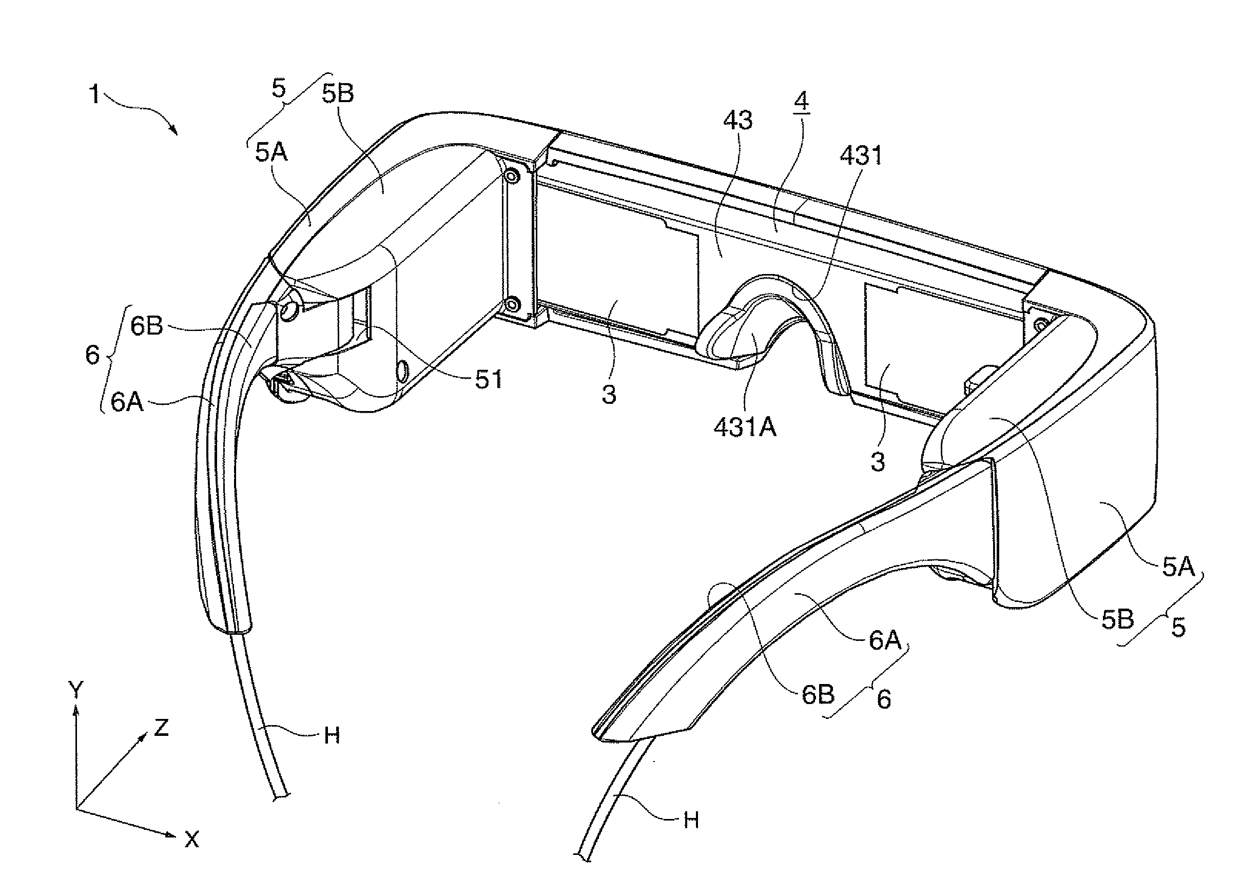
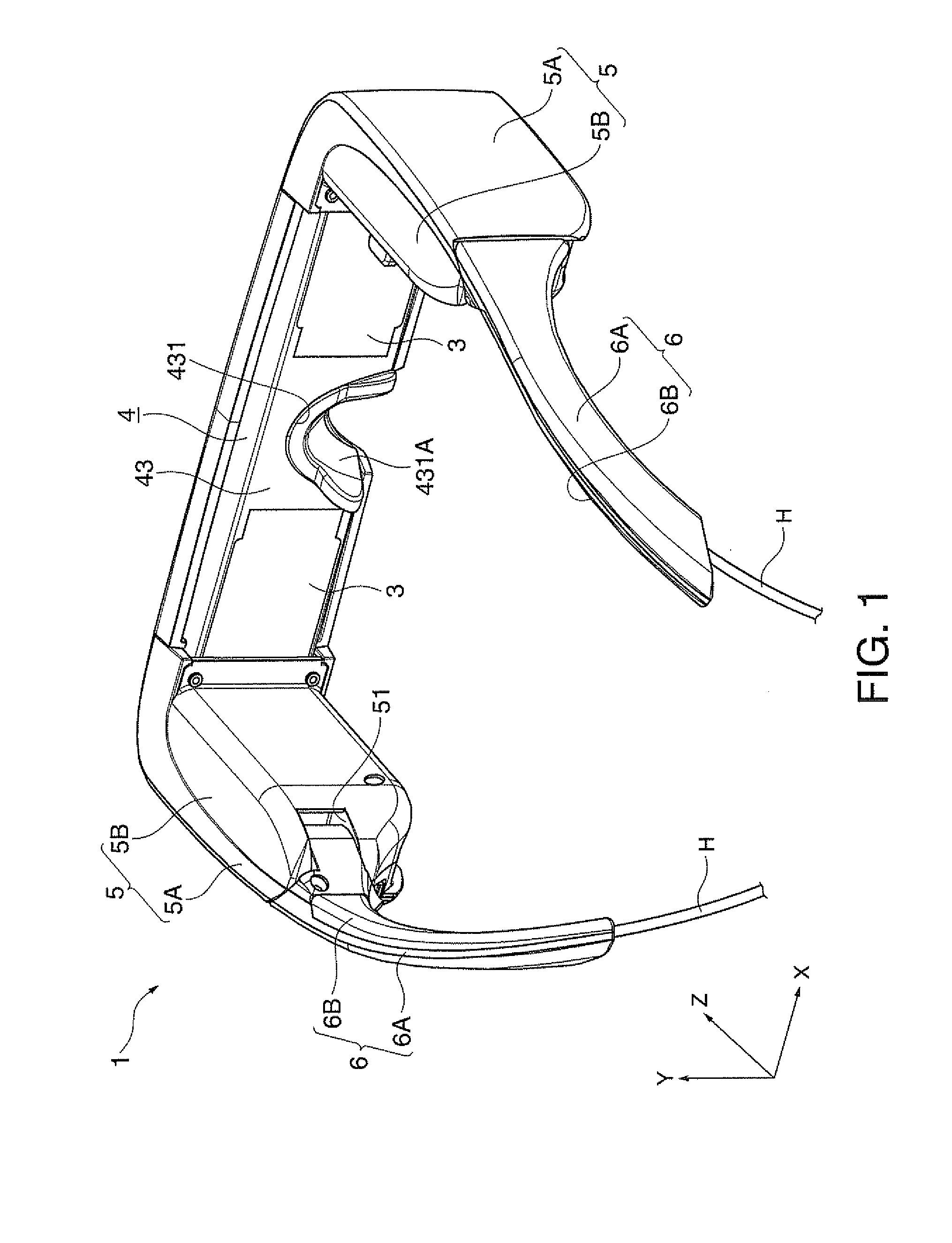
[0050]FIG. 1 is a perspective view showing an appearance of a virtual image display system 1.

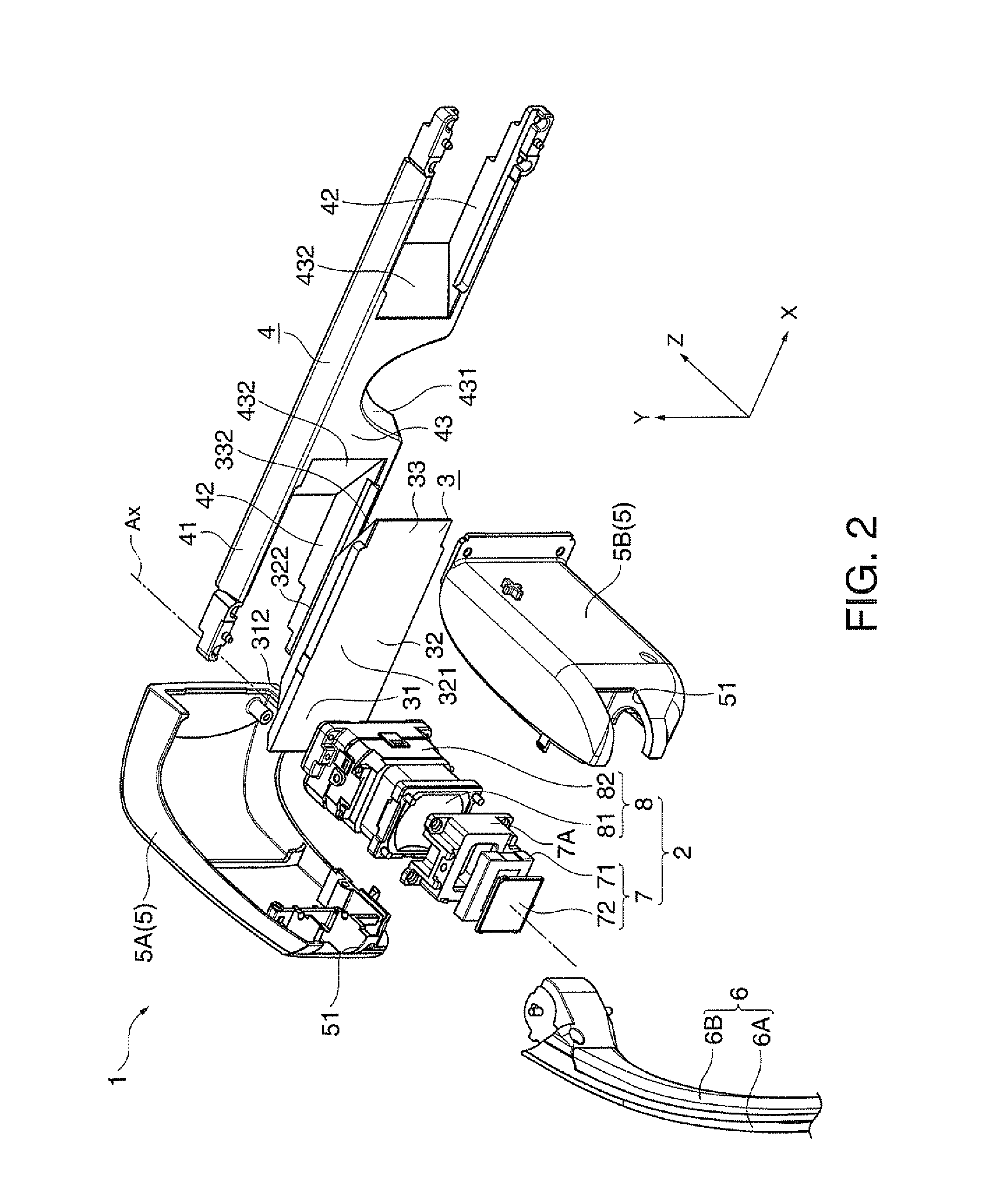
[0051]FIG. 2 is an exploded perspective view showing a configuration of the virtual image display system 1.

[0052]FIG. 3 is a perspective view showing an internal configuration of the virtual image display system 1.

[0053]Note that, in FIGS. 1 to 3, for convenience of explanation, an axis in parallel to an optical axis Ax (FIG. 2) of a projection lens 81, which will be described later, is the Z-axis, and the horizontal axis orthogonal to the Z-axis is the X-axis, the vertical axis orthogonal to the Z-axis is the Y-axis. The same is applicable to the subsequent drawings. Further, regarding the Z-axis, the observer's side is the −Z-axis side and the side away from the observer is the +Z-axis side.

[0054]FIGS. 1 to 3 are the views as seen from the −Z-axis...


PUM


Abstract

A virtual image display system includes a display device outputting image light, a circuit substrate driving the display device based on an image signal, a signal line connected to the circuit substrate and inputting the external image signal to the circuit substrate, a projection optical device projecting the image light from the display device, a light guide plate taking in the projected image light, and then, guiding the light to an external predetermined position, a housing member having a housing space housing respective members, and a first space communicated with the housing space and housing a part of the signal line inside, and a temple rotatably attached to the housing member via a hinge mechanism and having a second space communicated with the first space via the hinge mechanism inside. The signal line is routed from the first space into the second space via the hinge mechanism.

Description

BACKGROUND[0001]1. Technical Field[0002]The present invention relates to a virtual image display system such as a head-mounted display mounted on a head of an observer.[0003]2. Related Art[0004]In related art, a virtual image display system (image display system) having an appearance of eyeglasses for an observer to observe an image formed by a display device such as an LCD (Liquid Crystal Display) as a virtual image using an optical system has been proposed (for example, see Patent Document 1 (JP-A-2006-162767)).[0005]The virtual image display system disclosed in Patent Document 1 includes an image display unit having a display device (LCD or the like), a drive circuit, a projection lens (objective lens), etc. and fixed to a temple of an eyeglass frame, and a light guide plate (substrate) fixed to the front of the eyeglass frame.[0006]The image display unit (drive circuit) inputs a signal from outside via a cable (signal line) and allows the display device to form image light.[0007...

Claims


Application Information

Patent Timeline
Patent Type & Authority Applications(United States)
IPC IPC(8): G09G5/00
CPCG02B6/00G02B27/0172G02C5/22G02B2027/0178G02B27/0176
Inventor FUJISHIRO, TAKESHI
Owner SEIKO EPSON CORP
Why Eureka
Try Eureka