Electrode inspection apparatus for spot welding

a technology for inspection apparatuses and electrodes, which is applied in the direction of electrode maintenance, television systems, instruments, etc., can solve the problems of deterioration of the tip condition and inability to ensure the quality of welded parts, and achieve accurate measurement, reduce availability ratio, and accurate performance

Active Publication Date: 2012-08-09
KEYLEX CORP
View PDF7 Cites 24 Cited by
  • Summary
  • Abstract
  • Description
  • Claims
  • Application Information

AI Technical Summary

Benefits of technology

[0022]According to the first aspect of the present invention, a distance from the electrode to the camera through the mirror is constant, and therefore, variations of the measured values are less likely to occur. Besides, the image of the tip of the electrode can be captured by the camera from the direct front thereof, and therefore, the captured image is processed by the calculation section, thereby measuring at least two or more tip diameters at one time. With this process, the measurement of the diameters of the electrode tip, i.e., determination of whether the tip has a true circular shape or not, is accurately performed without reducing availability ratio in a production line.
[0023]According to the second aspect of the present invention, both surfaces of the mirror reflect the respective tips of the electrodes at the same time, whereby images of the tips of the pair of the electrodes are captured simultaneously, and the diameters of the electrode tip is accurately measured without reducing availability ratio in the production line. Since the camera is not disposed between the pair of the tips of the electrodes, and only the mirror is disposed between the electrodes, a width of a portion of t

Problems solved by technology

However, after the welding is done a predetermined times, the tips of the electrodes do not have the true circular shape due to wear, or oxide coatings and the like are attached to

Method used


Image

  • Electrode inspection apparatus for spot welding
  • Electrode inspection apparatus for spot welding
  • Electrode inspection apparatus for spot welding

Examples


first embodiment

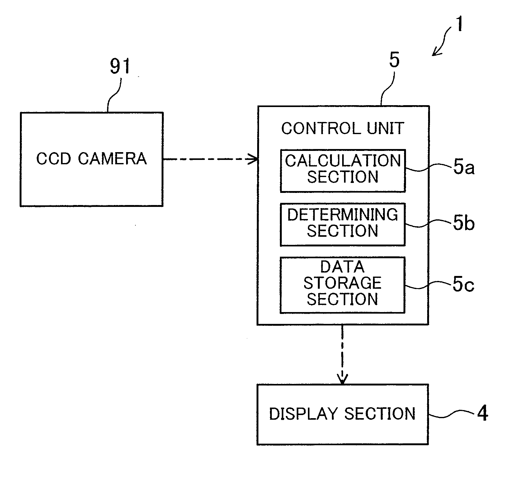
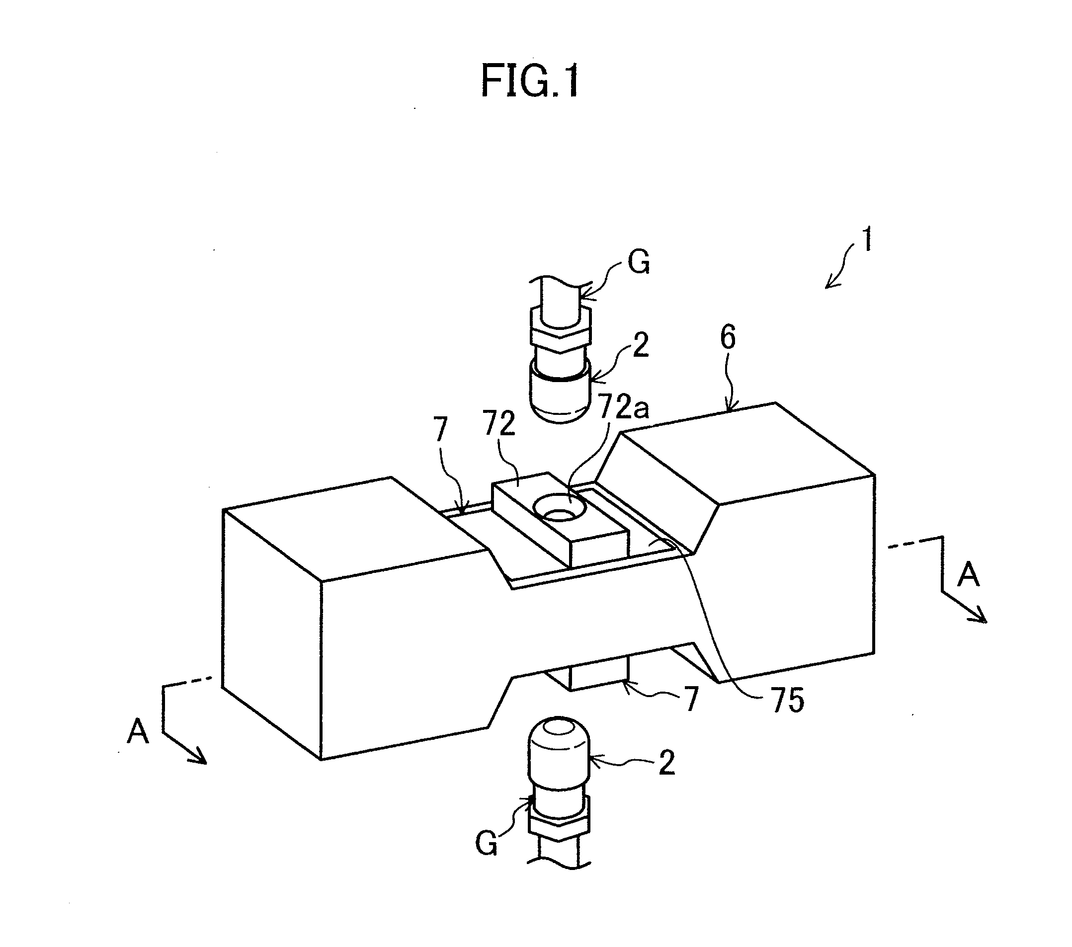
[0053]FIGS. 1-5 show an electrode inspection apparatus 1 for spot welding according to a first embodiment. This electrode inspection apparatus 1 is used for inspecting conditions of a pair of electrodes 2 made of chromium-copper or the like and mounted on and held to tips of a weld gun G used when steel plates are welded together by spot welding in automobile production lines. The electrode inspection apparatus 1 includes an inspection apparatus body 6 formed by processing steel plates.

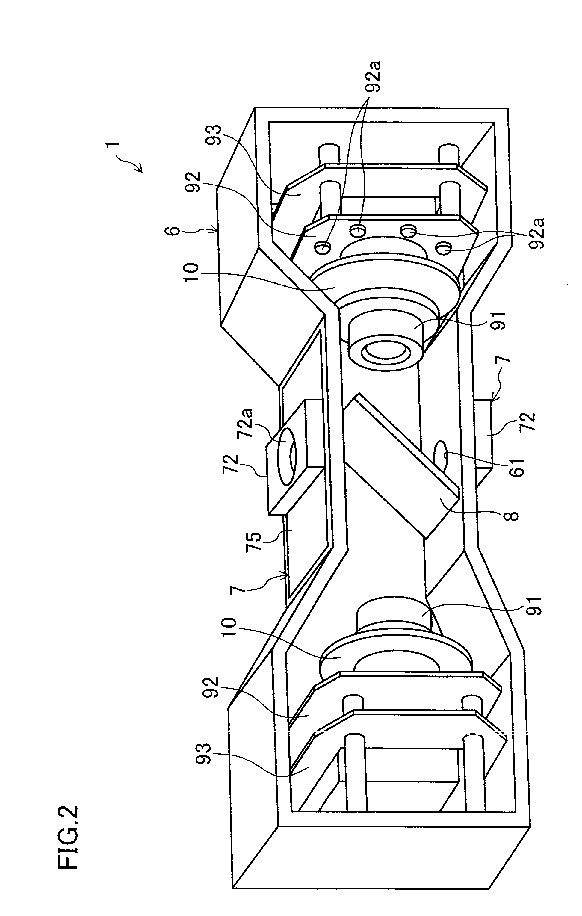
[0054]The inspection apparatus body 6 is formed into a box shape of a substantially rectangular parallelepiped extending in a horizontal direction. Central portions of both upper and lower walls in the longitudinal direction are recessed, the distance between the central portions in the longitudinal direction are narrower than the distance between portions at both sides in the longitudinal direction. The outer shape of the inspection apparatus body 6 is vertically symmetrical. Each of the recessed cen...

second embodiment

[0083]FIG. 11 shows an electrode inspection apparatus 1 for spot welding according to a second embodiment. The second embodiment has the same construction as in the first embodiment other than providing one single CCD camera 91 to reduce the length of an inspection apparatus body 6 in the longitudinal direction, and changing the structure of a minor 81. Therefore, the different parts will be specifically described hereinafter.

[0084]The minor 81 is formed into a plate shape, and is rotatably attached to the inside of the inspection apparatus body 6 by a rotation axis extending in the width direction of the inspection apparatus body 6. The minor 81 is obliquely disposed with respect to an electrode 2 so as to be distant from a fixing hole 72a at a position opposite to the electrode 2 with respect to a measuring reference unit 7, and is configured to rotate 90 degrees around the rotation axis 81a, thereby switching between the electrode 2 in an upper side to be captured by the CCD came...

third embodiment

[0086]FIG. 12 shows an electrode inspection apparatus 1 for spot welding according to a third embodiment. The third embodiment has the same construction as in the second embodiment other than changing a structure of a mirror 82. Therefore, the different parts will be specifically described hereinafter.

[0087]The mirror 82 includes an upper mirror 82a and a lower mirror 82b each formed into a plate shape. The upper mirror 82a is obliquely disposed with respect to an electrode 2 so as to be distant from a fixing hole 72a at a position opposite to the electrode 2 with respect to a measuring reference unit 7 located in the upper side, and the lower mirror 82b is obliquely disposed with respect to the electrode 2 so as to be distant from a fixing hole 72a at a position opposite to the electrode 2 with respect to a measuring reference unit 7 located in the lower side. The mirror 82a and the lower mirror 82b are integrated at a side closer to the CCD camera 91, and has a V shape in cross-se...


PUM

PropertyMeasurementUnit
Diameteraaaaaaaaaa
Distanceaaaaaaaaaa

Abstract

An electrode inspection apparatus for spot welding is provided for precisely measuring diameters of a tip of an electrode without reducing availability ratio in a production line, and is particularly useful when inspecting a weld gun having electrodes with a narrow distance therebetween.
A CCD camera 91 for imaging the tip of the electrode held to the weld gun is disposed in an inspection apparatus body 6. The inspection apparatus body 6 includes a measuring reference unit 7 in which a fixing hole 72a for fixing the tip of the electrode is formed, and a mirror 8 obliquely arranged with respect to the electrode so as to be distant from the fixing hole 72a at a position opposite to the electrode with respect to the measuring reference unit 7. The CCD camera 91 is disposed in a side of the mirror 8 with a distance therebetween for imaging the tip of the electrode from a direct front thereof reflected on the mirror 8 by reflection.

Description

TECHNICAL FIELD[0001]The present disclosure relates to electrode inspection apparatuses for spot welding used in, for example, automobile production lines.BACKGROUND ART[0002]Conventionally, spot welding techniques of pressing electrodes mounted on and held to tips of a weld gun to steel plates, applying a pressure thereto, and causing energization to provide resistance heating to the steel plates to weld them together have been used in automobile production lines. The spot welding techniques ensure reliability of products with proper management of current values during welding, weld times, applied pressure force, and conditions of tips of the electrodes. Among these elements, the tips of the electrodes ensure welding quality most stably if they have a true circular shape and do not include waste materials attached thereto. However, after the welding is done a predetermined times, the tips of the electrodes do not have the true circular shape due to wear, or oxide coatings and the l...

Claims


Application Information

Patent Timeline
IPC IPC(8): H04N7/18
CPCG01B11/08B23K11/3063B23K11/30B23K11/36
Inventor YAMANE, TOSHIMASAYAMANE, YOSHIAKI
Owner KEYLEX CORP
Why Eureka
Try Eureka