
Urinary catheter and method

Inactive Publication Date: 2012-08-09
SCHANZ RICHARD W +1
View PDF46 Cites 8 Cited by
  • Summary
  • Abstract
  • Description
  • Claims
  • Application Information

AI Technical Summary

Benefits of technology

[0016]In one embodiment, the catheter has its inner and outer surfaces coated with silver and zinc to reduce infection. In another embodiment, the outer surfaces of the catheter are coated with an antibiotic impregnated silicone to reduce over growth of bacteria.
[0017]The catheter is preferably made of a flexible material resistant to bacterial adhesion. Typical flexible materials are silicone, rubber, latex, and thermoplastic elastomers. Silicone has the advantage of being inert and unreactive to body fluids.
[0018]The catheter is placed within a patient by employing the above catheter in the stiffened state with the spine in place to aid in positioning the first end of shaft within the urethra and bladder of the patient. When positioned, the spine is removed and the ballooning securing tip is inflated to secure the inlet of the liquid drain passageway within the bladder to collect and insure that urine is drained through the liquid drain passageway and out the drain outlet.
[0021]The catheter thus provides a simple to use device, which has the placement advantages of a stiffened catheter, but the comfort of a flexible catheter. The catheter thus provides the advantages of hard and flexible catheters without the need for a placement guide or device.

Problems solved by technology

However, an individual that has to use a catheter for a longer period of time finds that it is discomforting.
If the person is a truck driver or an equipment operator where the vibrations transmit into the body especially when sitting through the seat of the pants, the catheter presents many problems.
The firmness of the shaft of the typical catheter creates the sensation of sitting on a rod and will soon change from being very uncomfortable to inflammation and possibly resulting in infection.

Method used


Image

  • Urinary catheter and method
  • Urinary catheter and method

Examples


Embodiment Construction

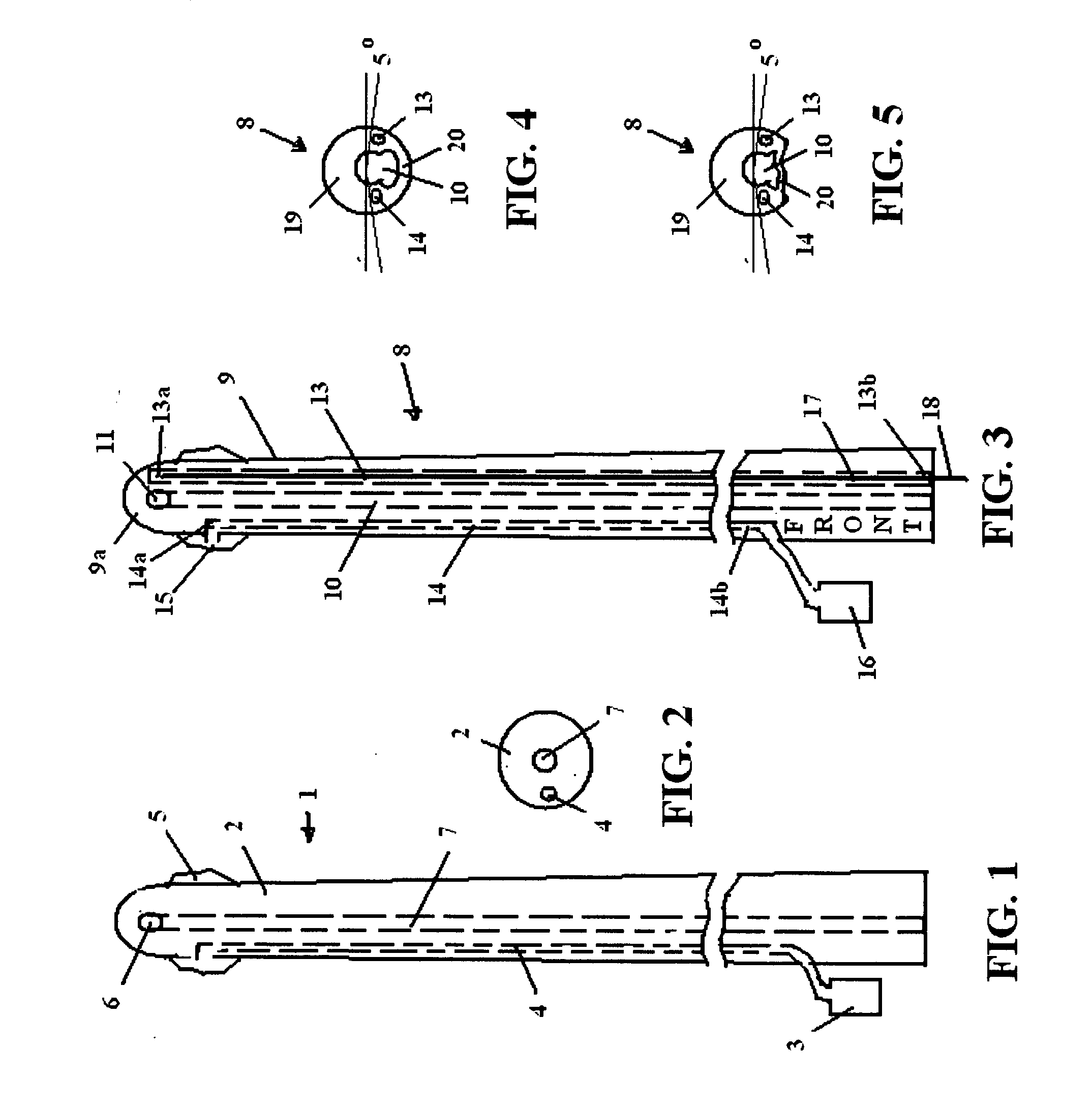
[0027]FIG. 1 is a cross-sectional side view of a conventional catheter 1 with unforgiving thick tubing 2. It uses an adapter 3 for injection of water through passageway 4 in communication with a balloon 5 attached to the tip of the tubing 2, which when inflated holds the catheter 1 in place. Urine flows through the opening 6 leading into a urine passageway 7 to a catheter bag (not shown). The sidewalls 2 of the catheter are firm so that the catheter can be inserted, causing discomfort over long use or sitting.

[0028]FIG. 2 is a cross sectional view of the catheter 1 of FIG. 1 showing that water passageway 4 and the urine passageway 7 are circular, and subject to pinching off when a user sits bending the catheter 1.

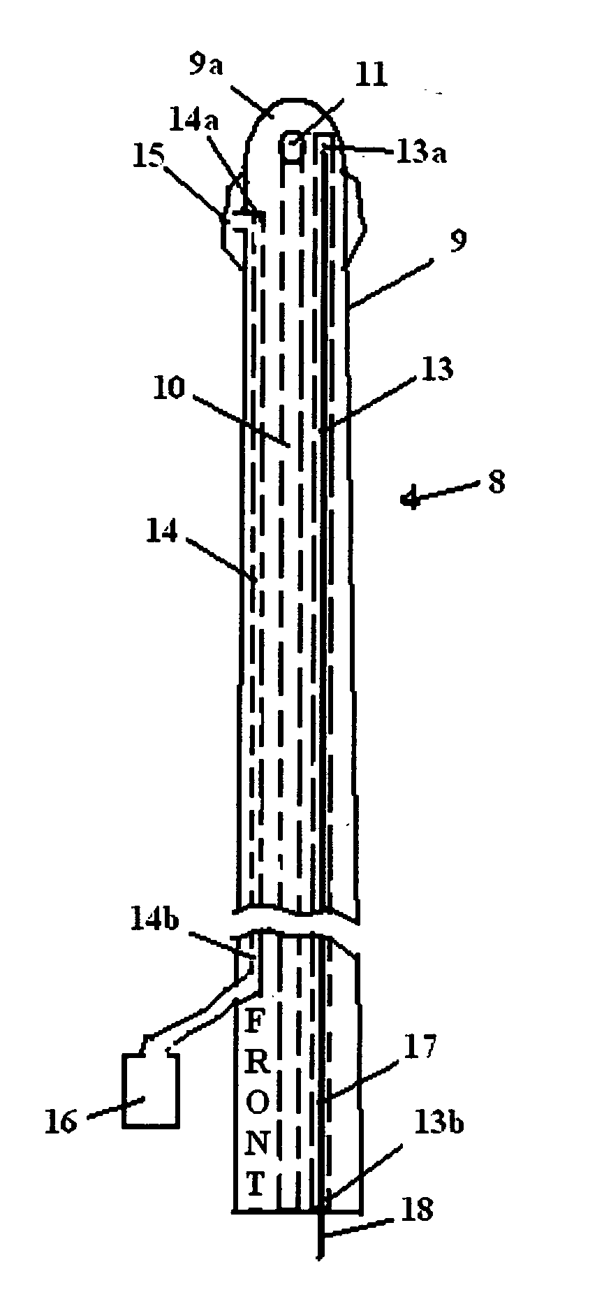
[0029]FIG. 3 is a cross-sectional side view of the present catheter 8. It has a shaft 9 of a length and diameter to be inserted within the urethra and extend into the bladder, with first and second ends 9a, 9b. The shaft 9 has a urine drain passageway 10 for transporting ur...


PUM


Abstract

A flexible removable catheter with varying bell-shaped cross sectional widths for insertion through the urethra extending into the bladder to allow urine to flow through a urine passageway into a catheter bag.

Description

BACKGROUND OF THE INVENTION[0001]1. Field of Invention[0002]This invention pertains to urinary catheters. More particularly it relates to a flexible removable catheter for insertion through the urethra extending into the bladder to allow urine to flow through the urine passageway.[0003]2. Description of Related Art[0004]A number of catheters to relieve urine retention are known. A urinary catheter is a tube that can be inserted through the urethra into the bladder to allow drainage. The process of inserting a catheter involves in most uses, insertion of a rigid delivery tube carrying a thin, flexible tube catheter (“soft” catheter), which is left in the urethra for draining. In other designs a larger, solid (“hard”) catheter is inserted.[0005]An individual who needs to use a catheter for a few days is not totally uncomfortable and is easily able to tolerate its uniqueness. However, an individual that has to use a catheter for a longer period of time finds that it is discomforting. T...

Claims


Application Information

Patent Timeline
IPC IPC(8): A61M27/00
CPCA61M25/0017
Inventor SCHANZ, RICHARD W.ELLSWORTH, J. BRYAN
Owner SCHANZ RICHARD W
Learn More