Shunt system with coating and flow restricting component exerting a passive and essentially constant resistance to outflow

a technology of cerebrospinal fluid and shunt system, which is applied in the field of improved cerebrospinal fluid shunt system, can solve the problems of increased development of loculated csf compartments, death after shunt infection, and siphoning from the ventricle to unphysiological resorption sites, so as to reduce the number of shunt infections, reduce the risk of shunt infection, and encourage coagulation and (possibly fatal) blood clotting

Inactive Publication Date: 2007-05-17
SINU SHUNT
View PDF5 Cites 47 Cited by
  • Summary
  • Abstract
  • Description
  • Claims
  • Application Information

AI Technical Summary

Benefits of technology

[0047] The improved coated shunt system disclosed herein has been found to advantageously and surprisingly reduce many of the problems associated with current shunts. Metals and other less biocompatible materials encourage coagulation and (possibly fatal) blood clotting in conventional shunts, however biocompatible coatings allow the problem of “recognition” of the non-biocompatible material by the individual's body to be avoided.
[0048] It is envisaged that shunt infection may be reduced by the advantageous coatings on the shunt disclosed herein, which will reduce adhesion of cells and other biological matter to the shunt and improve biocompatibility with the patient. Mechanical failure is reduced by the simplistic shunt design, as there is a shorter distance in this system between the ventricles and resorption site, and also no need for complex pressure valves. Mechanical failure is also reduced by some coatings which themselves have advantageous structural properties. Mechanical failure is also reduced by the fact that the coating can be used to coat less biocompatible, but structurally stronger, materials. This may also lead to decreased disconnection problems. This innovation is also thought to reduce infection rates because there is a smaller length for the CSF to travel, which, for example, leads to a reduced surface for biofilm formation. The biocompatibility of the shunt coatings disclosed herein also lead to a reduction in shunt rejection in patients. Obstruction of the shunt is also reduced due to decreased adhesion of one or more of brain cells, the choroid plexus, tumor cells and protein buildups.
[0049] Functional failure is reduced by the use of the sagittal sinus or transverse sinus as a resorption site, which allows the pressure difference over the CSF shunt system to remain essentially constant. Thus, in contrast to many of the shunt types in use today, the present invention does not rely on control of flow via “pressure control”—instead it functions on an entirely different principle: maintenance of a constant resistance to CSF flow. This would not be the case for resorption sites such as the peritoneum. Furthermore, the pressure difference generated across the shunt is similar to the physiological pressure differences between the ventricles and the normal CSF resorption site, thus regulating the CSF flow to be within the normal range and avoiding hyperdrainage. Posture-related pressure changes across the shunt are also beneficially avoided.

Problems solved by technology

Unfortunately, once a shunt is infected, it is almost always necessary to remove it and insert a temporary external ventricular drain.
Apart from the practical problems associated with the treatment of shunt infection, it has been shown that there is an increase in the development of loculated CSF compartments, impaired intellectual outcome, and death after shunt infection.
(c) Functional failure—The cause of functional failure is usually overdrainage.
The underlying problem is one of siphoning from the ventricle to unphysiological resorption sites, usually the peritoneum.
This overdrainage can result in subdural haematoma, low pressure symptoms (postural headache and nausea), and craniosynostosis.
Furthermore, when conventional shunts drain to the abdomen (ventriculo-peritoneal shunts), fluid may accumulate in the abdomen and / or abdominal organs may be injured.
(d) Obstruction—Obstruction, a common problem, usually occurs when something clogs the ventricular catheter.
Suboptimal placement can result in the catheter being clogged by brain cells or the choroid plexus.
Tumor cells and protein buildups can also cause obstruction, as the cells adhere to the sides of the shunt.
If the blockage is only partial or intermittent, the patient may experience periodic headaches, nausea and vomiting, drowsiness, listlessness, loss of appetite, and a general decrease in mental functioning.
Complete obstruction can cause these same symptoms, including the more severe signs of blurred vision, loss of coordination, and possible loss of consciousness.
Both these problems are due to mechanical weakness of the materials used.
(f) Shunt rejection—Another common problem with shunts is that ions or particles from the shunt may enter the body and cause shunt rejection or inflammation.
Serious and long-term complications of shunt implantation may also include bleeding under the outermost covering of the brain (subdural hematoma).
Metals and other less biocompatible materials may encourage coagulation and (possibly fatal) blood clotting in conventional shunts, due to “recognition” of the foreign material by the individual's immune system.
However, infected shunts still may have to be surgically removed, which is clearly undesirable.
Tissue engineered shunts have been proposed to improve biocompatibility, however there are as yet unresolved problems with the polymer types, cell type, and cell densities used (Lee I-W et al.
Bayston R., Lambert E. J Neurosurg 87 247-251 1997), however one problem with this shunt design is that the antimicrobial effect is not necessarily as long-lasting as the implanted shunt.
However, these types of materials have recently been shown to have a higher likelihood of purulent infection (“Pathogenesis and Prevention of Catheter-Related Infection”, Sherertz, R J, speaker at the “Shunt Technology: Challenges and Emerging Directions” conference, National Naval Medical Center, Bethesda, Md., USA, Jan. 8, 1999), probably as neutrophils are caused to migrate differently, which also leads to a higher inflammatory index and increased complement activation within the patient.

Method used


Image

  • Shunt system with coating and flow restricting component exerting a passive and essentially constant resistance to outflow
  • Shunt system with coating and flow restricting component exerting a passive and essentially constant resistance to outflow
  • Shunt system with coating and flow restricting component exerting a passive and essentially constant resistance to outflow

Examples


Embodiment Construction

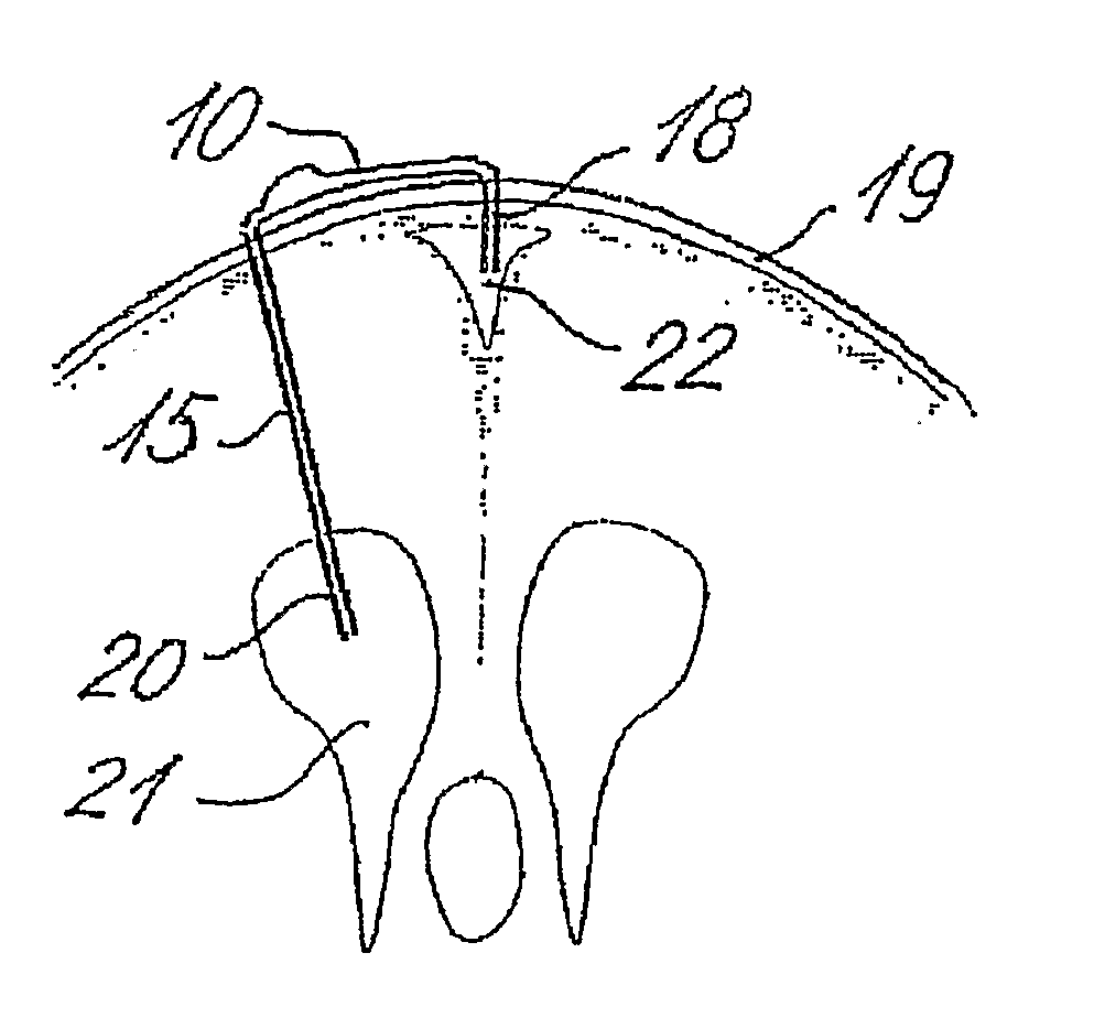
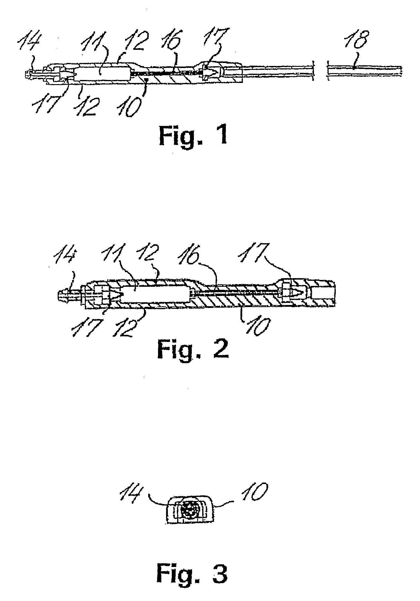
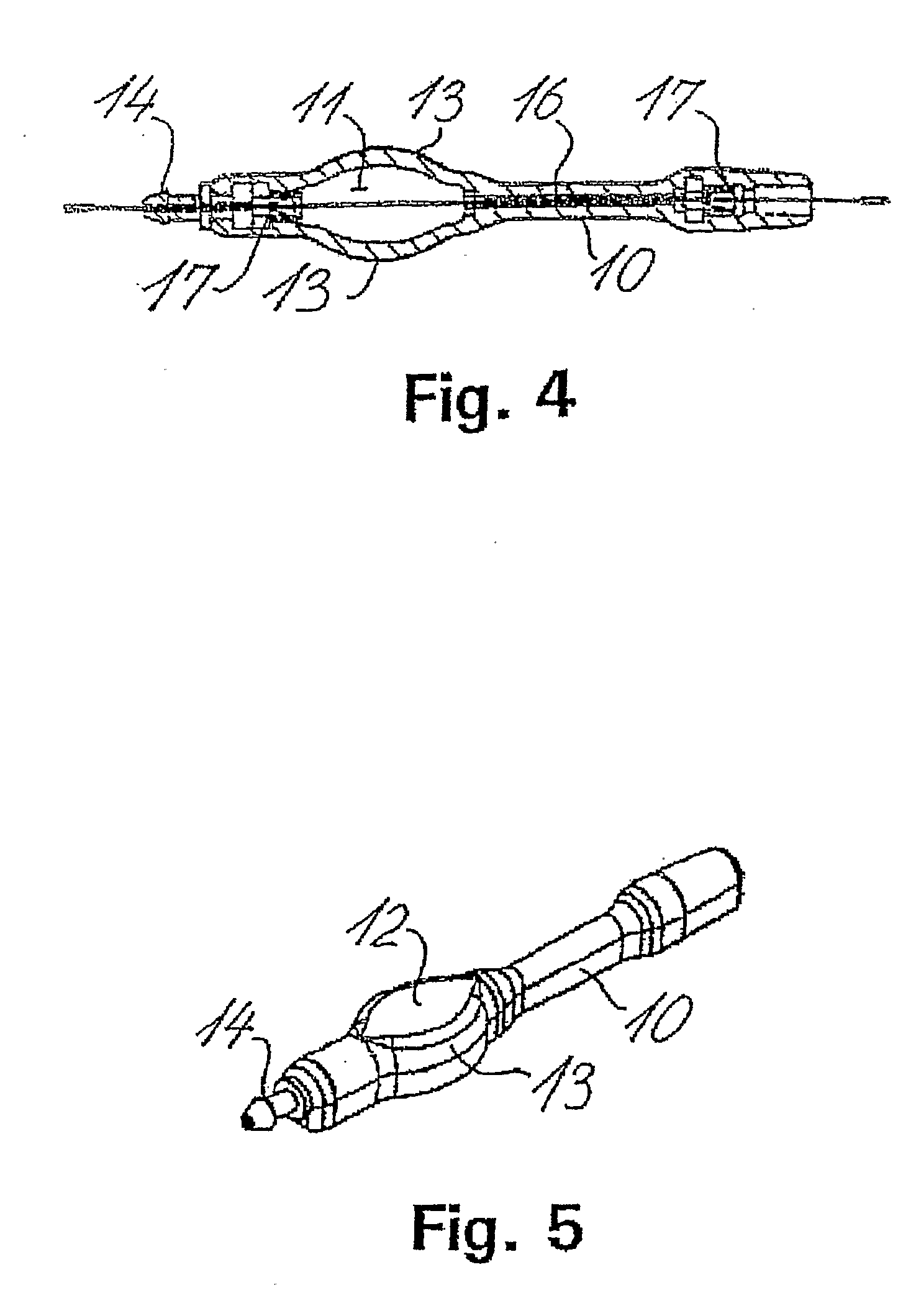
[0065] The shunt system provided in the present invention comprises a shunt body allowing fluid communication between a brain ventricle and a part of the sinus system of the individual. Said shunt body comprises a flow restricting component capable of maintaining a passive and essentially constant resistance to flow of cerebrospinal fluids through the shunt body. Preferably, said essentially constant resistance to flow of cerebrospinal fluids through the flow restricting component is of a constant value of less than 8 mm Hg / ml / min.

[0066] Said shunt system also comprises a brain ventricle catheter capable of being connected to the shunt body at a first location thereof. The brain ventricle catheter is capable of draining cerebrospinal fluids from a brain ventricle to the shunt body.

[0067] Said shunt system also comprises a sinus catheter capable of being connected to the shunt body at a second location thereof. Said sinus catheter is capable of draining to the sinus system of the i...


PUM

PropertyMeasurementUnit
internal radiusaaaaaaaaaa
internal diameteraaaaaaaaaa

Abstract

The present invention relates to an improved cerebrospinal fluid shunt system comprising a coating covering at least part of the system and a flow restricting component exerting a passive and essentially constant resistance to flow. The present invention also relates to methods for implanting different catheters of a cerebrospinal fluid shunt system into a brain ventricle and the sinus system, respectively, of an individual. The present invention further relates to methods for shunting cerebrospinal fluid from a brain ventricle to the sinus system of an individual.

Description

[0001] All patent and non-patent references cited in the present patent application is hereby incorporated in their entirety. This application is a non-provisional of U.S. provisional application Ser. No. 60 / 524,892 filed 26 Nov. 2003, which is hereby incorporated by reference in its entirety.FIELD OF INVENTION [0002] The present invention relates to an improved cerebrospinal fluid shunt system comprising a coating covering at least part of the system and a flow restricting component exerting a passive and essentially constant resistance to flow. The coated shunt system is more resilient to wear and is better suited for implantation into the ventricles and the sinus system of the brain than conventional shunt systems. The passive and essentially constant resistance to outflow eliminates the need for using pressure sensitive valves and other mechanical components which are sensitive to wear. [0003] The present invention also relates to methods for implanting different catheters of a ...

Claims


Application Information

Patent Timeline
Patent Type & Authority Applications(United States)
IPC IPC(8): A61M5/00A61L27/16A61M5/168A61M27/00
CPCA61M5/16881A61M27/006
Inventor BORGESEN, SVEND ERIK
Owner SINU SHUNT
Why Eureka
Try Eureka