Method and apparatus for centration of an ocular implant

a technology of ocular implants and centration chambers, which is applied in the field of centration chambers of ocular implants, can solve the problems of 400 microns of error introduced in standard techniques for corneal inlay placement, and the inability to achieve consistent performance of small aperture devices, etc., and achieve the effect of accurate method and apparatus and increasing the depth of focus of the ey

Inactive Publication Date: 2012-08-09
ACUFOCUS
View PDF1 Cites 35 Cited by
  • Summary
  • Abstract
  • Description
  • Claims
  • Application Information

AI Technical Summary

Problems solved by technology

It has been discovered that the amount of error introduced in conventional techniques for corneal inlay placement may be too great for consistent performance of a small aperture device.
In particular, standard techniques can introduce as much as 400 microns of error due to parallax alone.

Method used


Image

  • Method and apparatus for centration of an ocular implant
  • Method and apparatus for centration of an ocular implant
  • Method and apparatus for centration of an ocular implant

Examples


Embodiment Construction

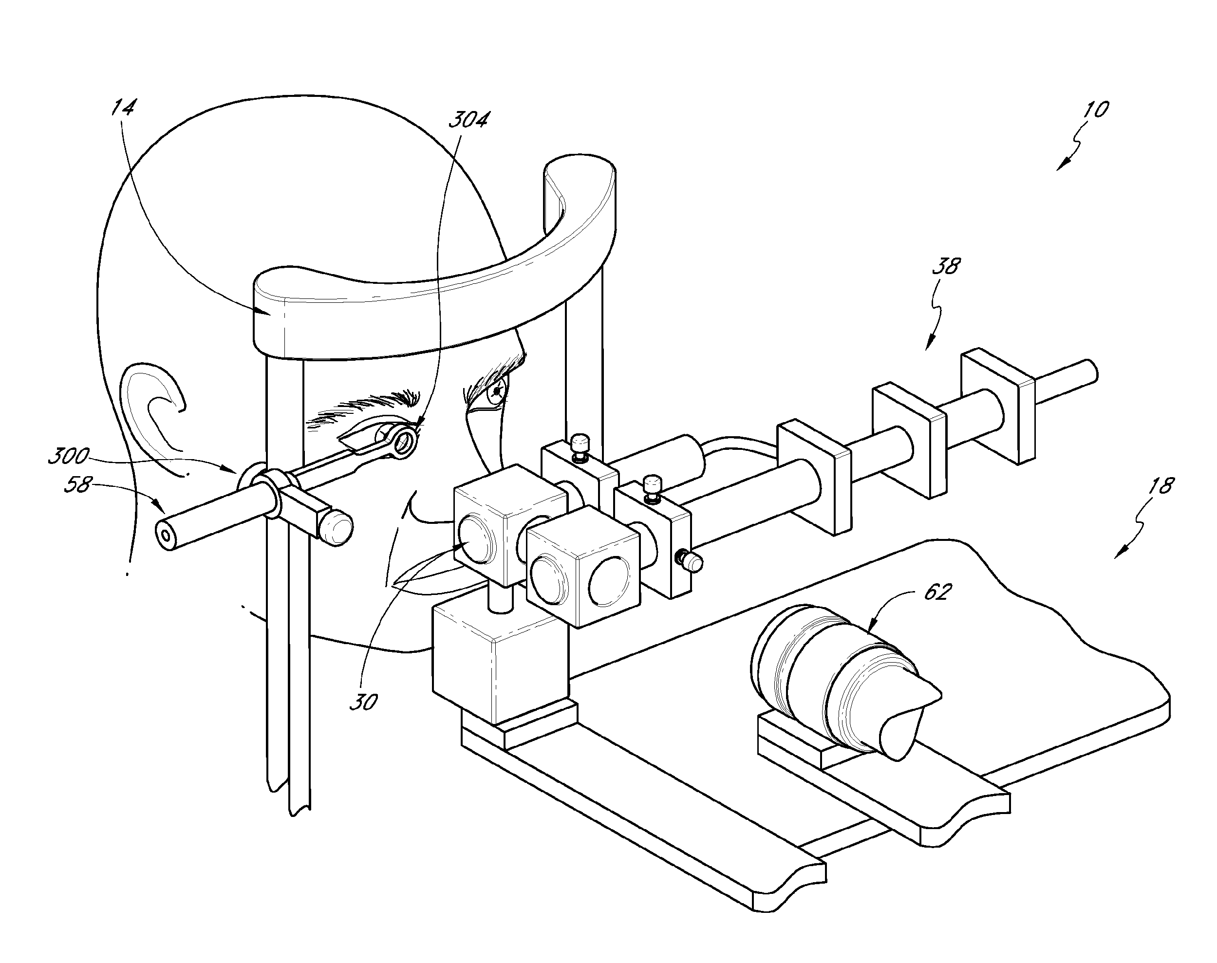
[0025]This application describes an apparatus and technique for identifying and marking a position corresponding to the intersection of a patient's line of sight with the anterior surface of the human cornea. The line of sight is an imaginary line from the eye to a perceived object as referenced by the person doing the viewing. Additional apparatuses and techniques for aligning a patient's line of sight are described in U.S. Publication No. 2005 / 0046794, published on Mar. 3, 2005, the entirety of which is hereby incorporated by reference. Features of these additional apparatuses and techniques can be used in combination with and / or can be substituted for features described herein.

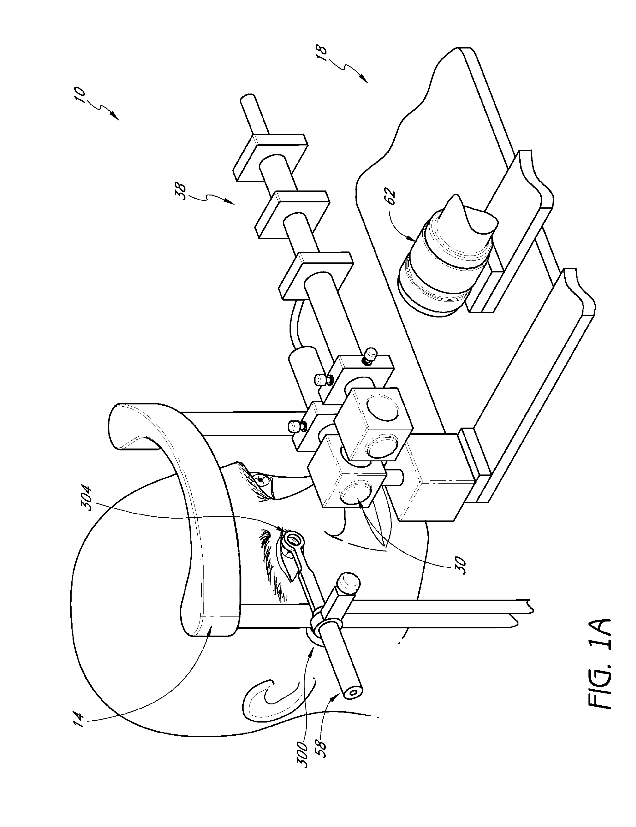
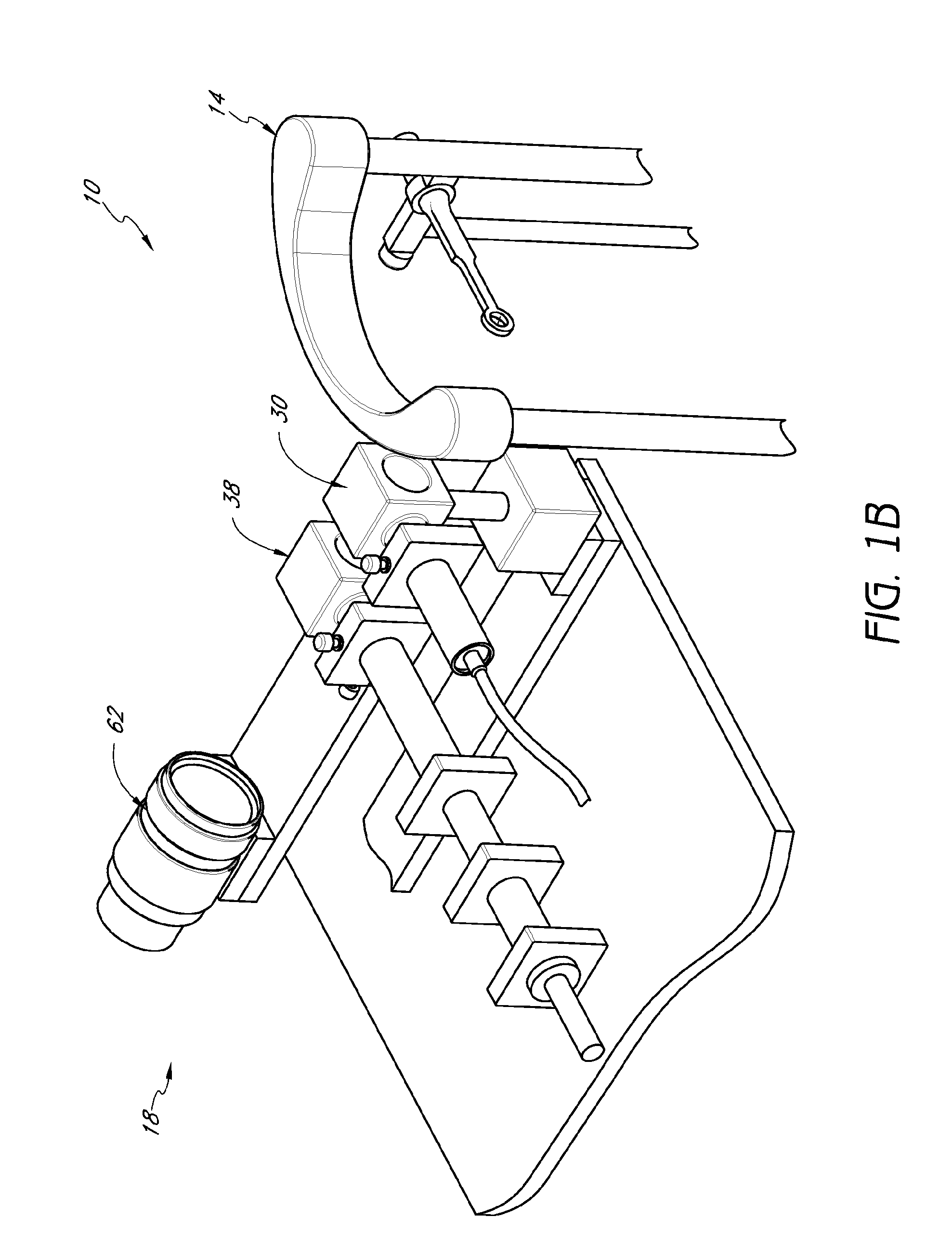
[0026]FIGS. 1A and 1B illustrate two views of an ocular inlay centration system 10. The system 10 includes a patient interface portion 14, a clinician data acquisition portion 18, and a plurality of optical components located therebetween. The optical components are configured to generate one or more center...


PUM


Abstract

This application describes apparatuses and techniques for identifying and marking a position corresponding to the intersection of a patient's line of sight with the anterior surface of the human cornea to aid centration of an ocular implant. The apparatus can include a first optical subsystem configured to project a first light through an aperture and along an instrument axis such that the patient will observe an annulus around a disc when the patient's visual axis is substantially collinear with the instrument axis and the patient will not observe the annulus when the visual axis is not substantially collinear with the instrument axis. The apparatus may also include a second optical subsystem configured to project a second light along the instrument axis such that the second light appears to a clinician to be an annulus around the first light.

Description

CROSS-REFERENCE TO RELATED APPLICATIONS[0001]This application claims the benefit of U.S. Provisional Application No. 61 / 251,253, filed Oct. 13, 2009, the entirety of which is hereby incorporated by reference.BACKGROUND OF THE INVENTION[0002]1. Field of the Invention[0003]This application relates to methods and apparatuses for aligning ocular implants (e.g., corneal inlays) with relevant anatomical structures (e.g., a patient's line of sight).[0004]2. Description of the Related Art[0005]Standard techniques for implanting corneal inlays involve the use of a surgical microscope. A Purkinje image is referenced through the microscope while moving the inlay into position. While this technique provides an approximation of alignment between the inlay and relevant ocular structures, various sources of error in alignment are introduced. For example, a parallax error can be introduced where a surgeon's vision is dependent on an image from a dominant eye.SUMMARY OF THE INVENTION[0006]It has bee...

Claims


Application Information

Patent Timeline
Patent Type & Authority Applications(United States)
IPC IPC(8): A61F9/00
CPCA61B3/152A61F9/0136A61F2/145
Inventor VUKICH, JOHN ALLANWEBB, KYLE
Owner ACUFOCUS
Why Eureka
Try Eureka