

Mechanism for bedding a receiver frame and/or a barrel in a stock of a firearm
- Summary
- Abstract
- Description
- Claims
- Application Information
AI Technical Summary
Benefits of technology
Problems solved by technology
Method used
Image

Examples
Embodiment Construction
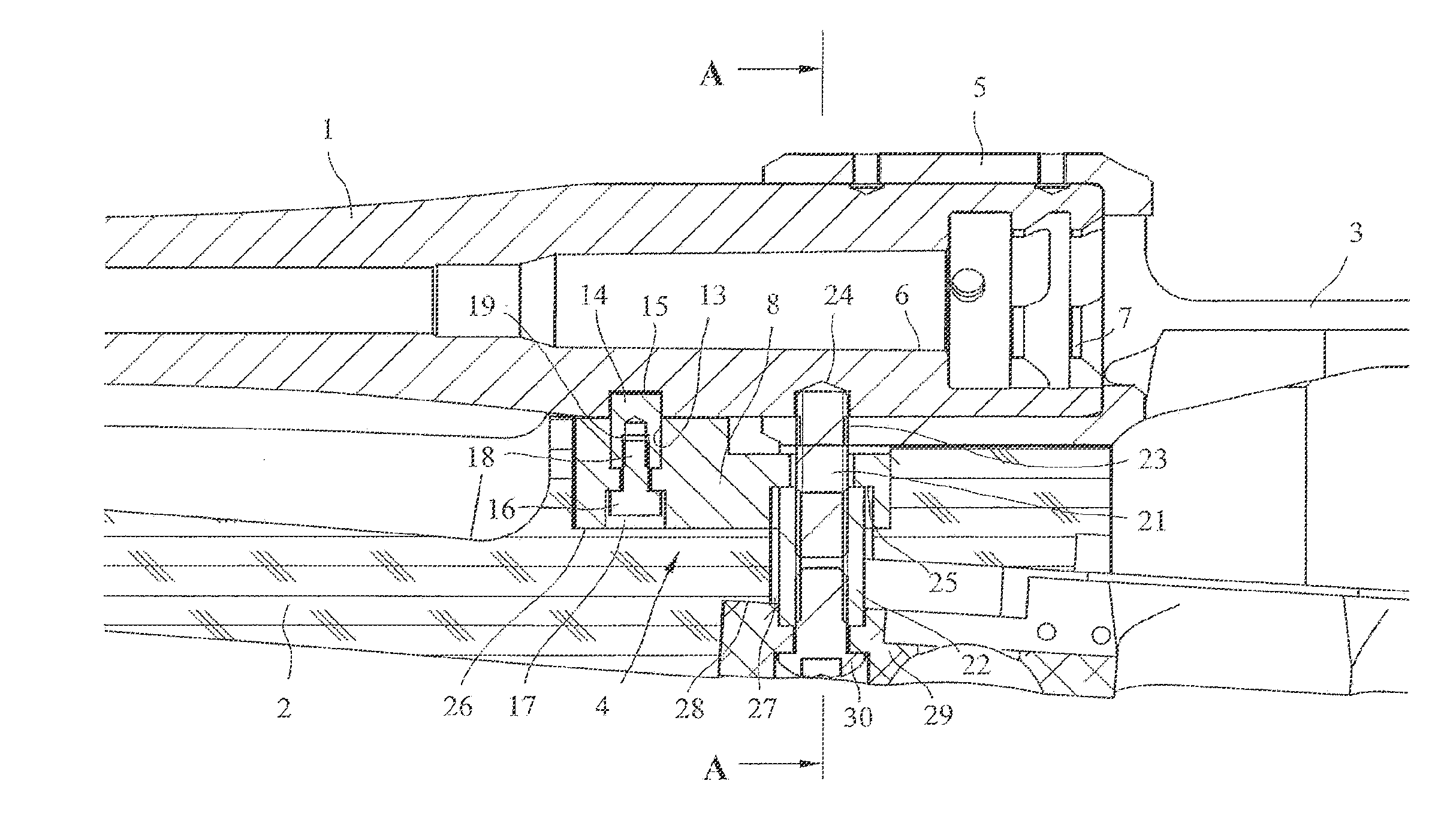
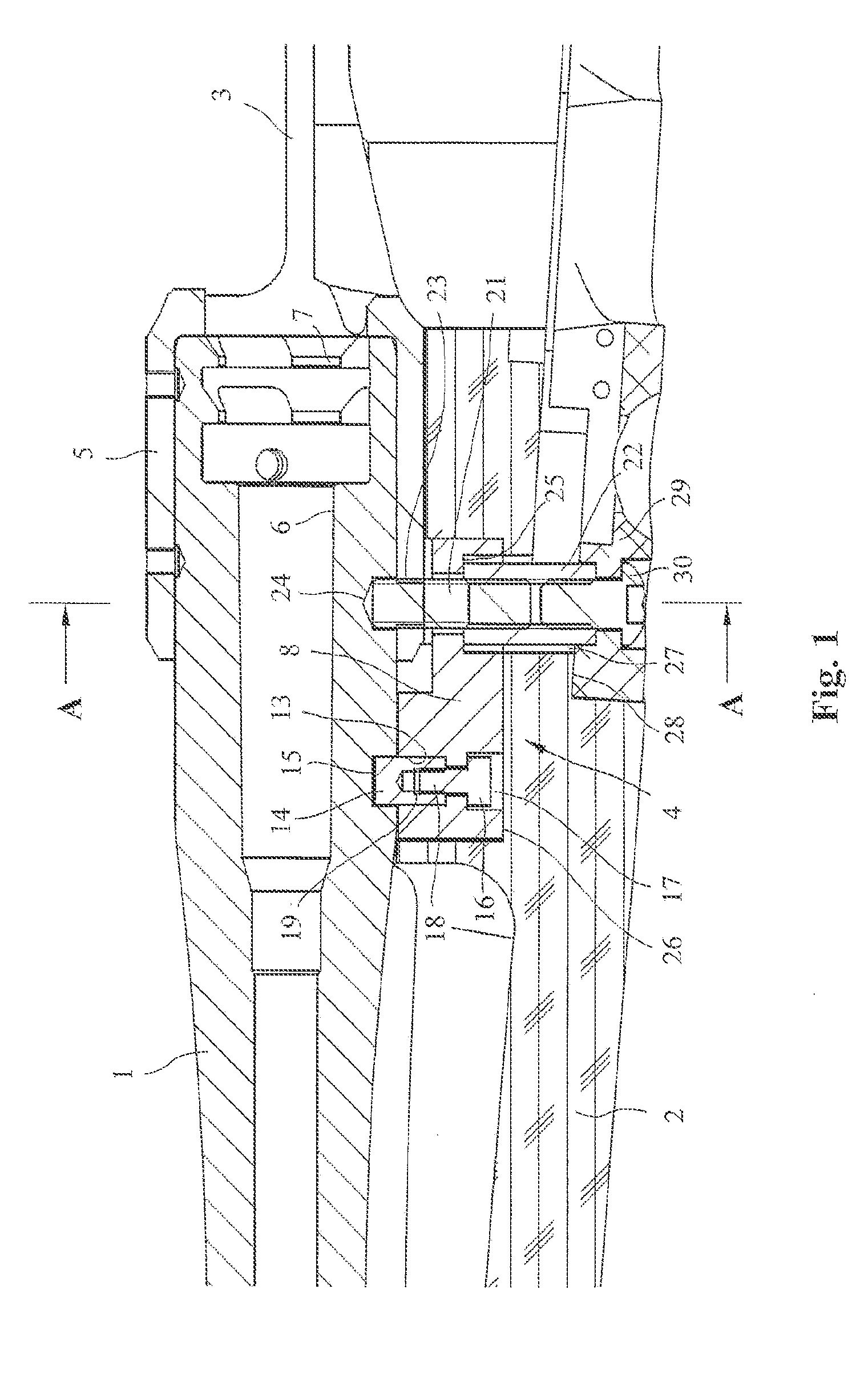
[0017]FIG. 1 shows a portion of a repeating rifle with a barrel 1, a stock 2, a system or receiver frame 3 and a mechanism 4 for bedding the system or receiver frame 3 in the stock 2. The system or receiver frame 3, here designed as a chamber sleeve, comprises a front end of the receiver 5 in which the back end of the barrel 1 comprising a cartridge chamber 6 and locking elements 7 is disposed.
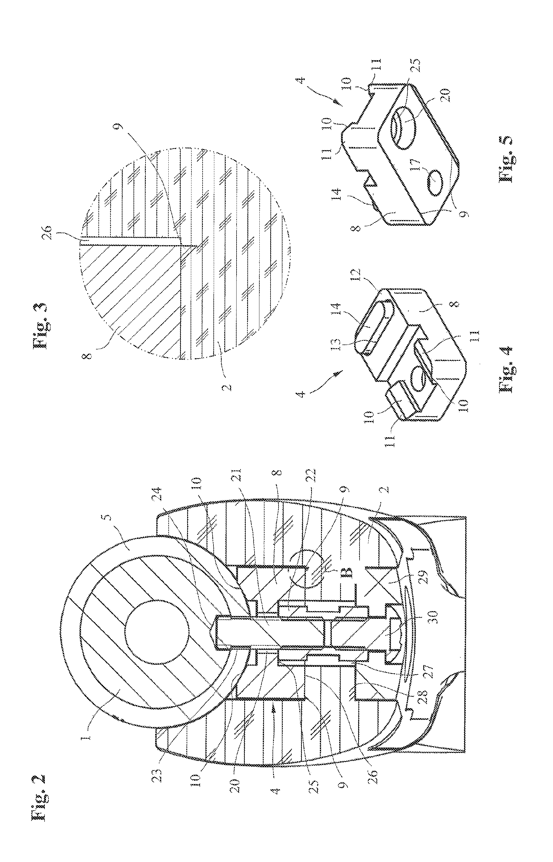
[0018]The mechanism 4 for bedding the receiver frame 3 in the stock 2, which mechanism is as separately shown in FIGS. 4 and 5, has an essentially cubic bearing component 8 which, on its lower surface, has rib-like guide members 9 that can be forced into the stock 2 so as to ensure that the bearing component 8 is seated free from play in the stock 2. Because of the rib-like guide members 9 which engage in the stock 2 so as to interlock with said stock, a guide profile for lateral guidance is created on the lower surface of the bearing component 8. As the embodiment shown in FIG. 2 indicates, t...
PUM
 Abstract
Description
Claims
Application Information