
Sample injector for liquid chromatograph

a liquid chromatograph and injector technology, applied in the direction of instruments, chemistry apparatus and processes, separation processes, etc., can solve the problems of slow method, sample remains, and failure to transfer the entire sample, so as to shorten the time for sample application and reduce the circumstances.

Inactive Publication Date: 2012-08-16
TELEDYNE INSTR INC
View PDF4 Cites 1 Cited by
  • Summary
  • Abstract
  • Description
  • Claims
  • Application Information

AI Technical Summary

Benefits of technology

[0006]It is a still further object of the invention to provide a system for shortening the time for sample application in preparatory chromatography.
[0007]It is a still further object of the invention to provide a novel sample injection method and apparatuses which reduce the circumstances under which an undesirable amount of sample fails to get injected.
[0010]In each of the above alternatives, the solvent is injected into the column through a straight path through said valve into the column, whereby blockage of the valve by sample is avoided. The valve element is rotated in the valve and includes a straight smooth passageway through the valve until an end of the smooth straight passageway is in communication with a sample cartridge and the other end is in communication with the column. In one embodiment, the sample is obtained in a container and poured into another container directly connected to the inlet of a piston pump. The sample is pumped from the container into the column. The sample may be poured from a flask into a container that is directly above the pump inlet or the sample may be poured into a syringe barrel. In one embodiment, the sample is injected by either of the above methods into a sample holder and solvent is applied through said sample holder and through a valve into a column, whereby the sample is injected into said column;
[0012]From the above description it can be understood that the apparatuses and methods of this invention have several advantages such as: (1) it is a quick and fast technique for injecting sample; and (2) it provides a more complete and better yield of sample from the flask in which the sample is prepared to the column.

Problems solved by technology

The method is slow and under some circumstances fails to transfer the entire sample.
Instead, some of the sample remains in the flask because it is difficult to get it into the pipette.
This prior art system also has the disadvantages of being difficult and slow failing to transfer the entire sample to the column.

Method used


Image

  • Sample injector for liquid chromatograph
  • Sample injector for liquid chromatograph
  • Sample injector for liquid chromatograph

Examples


Embodiment Construction

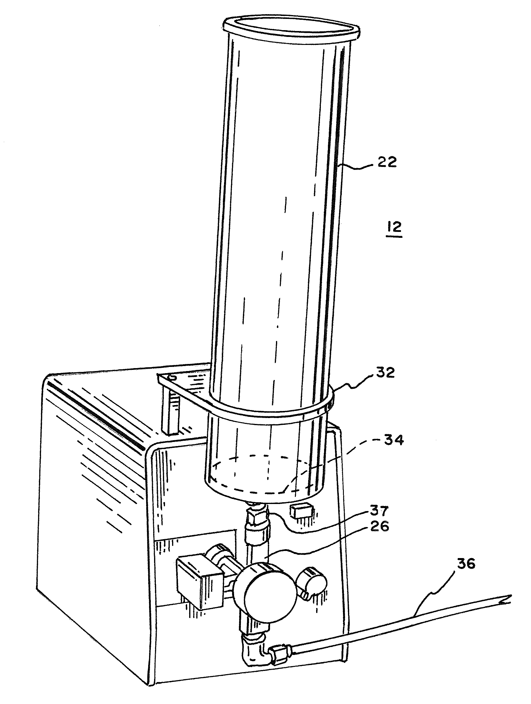
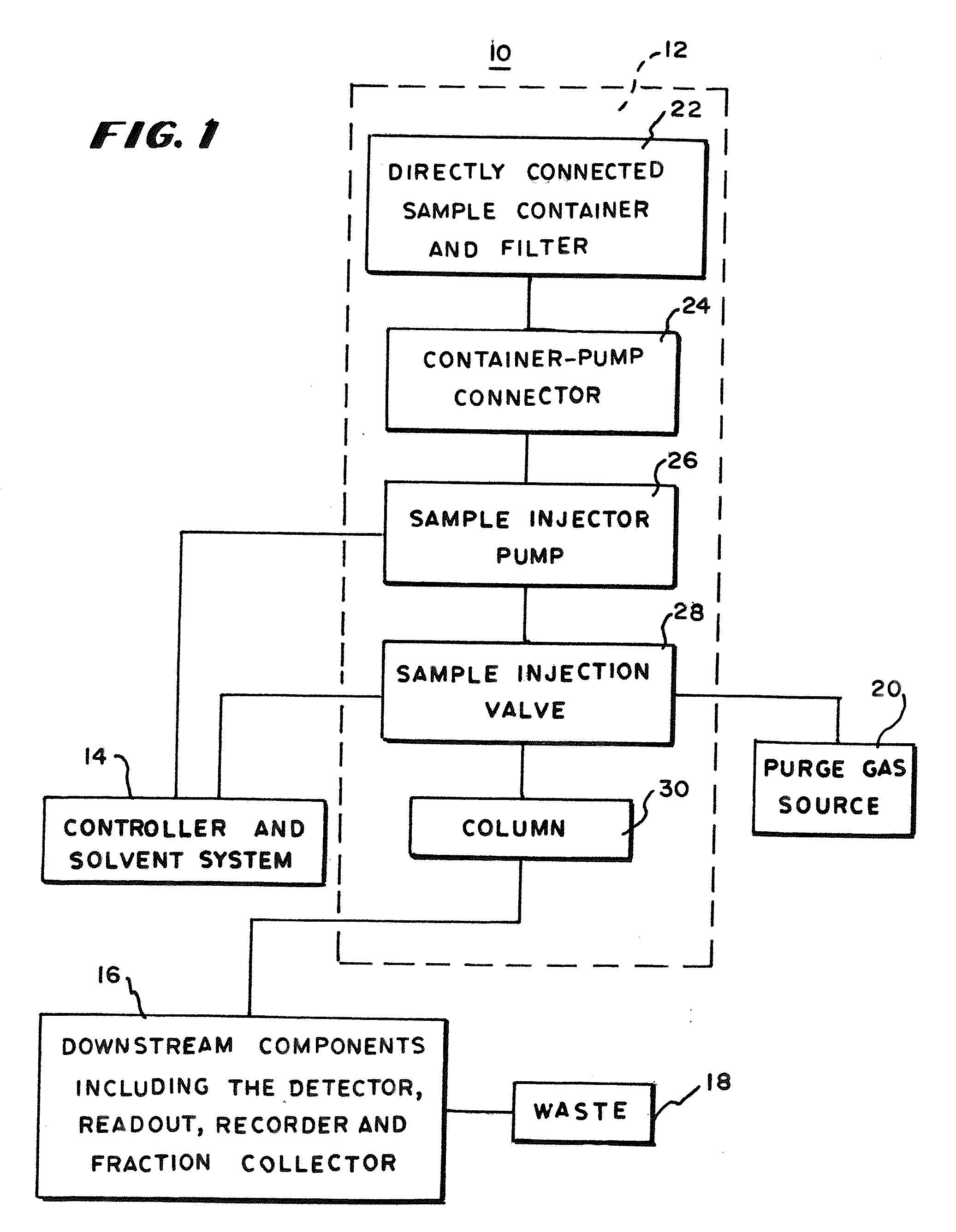
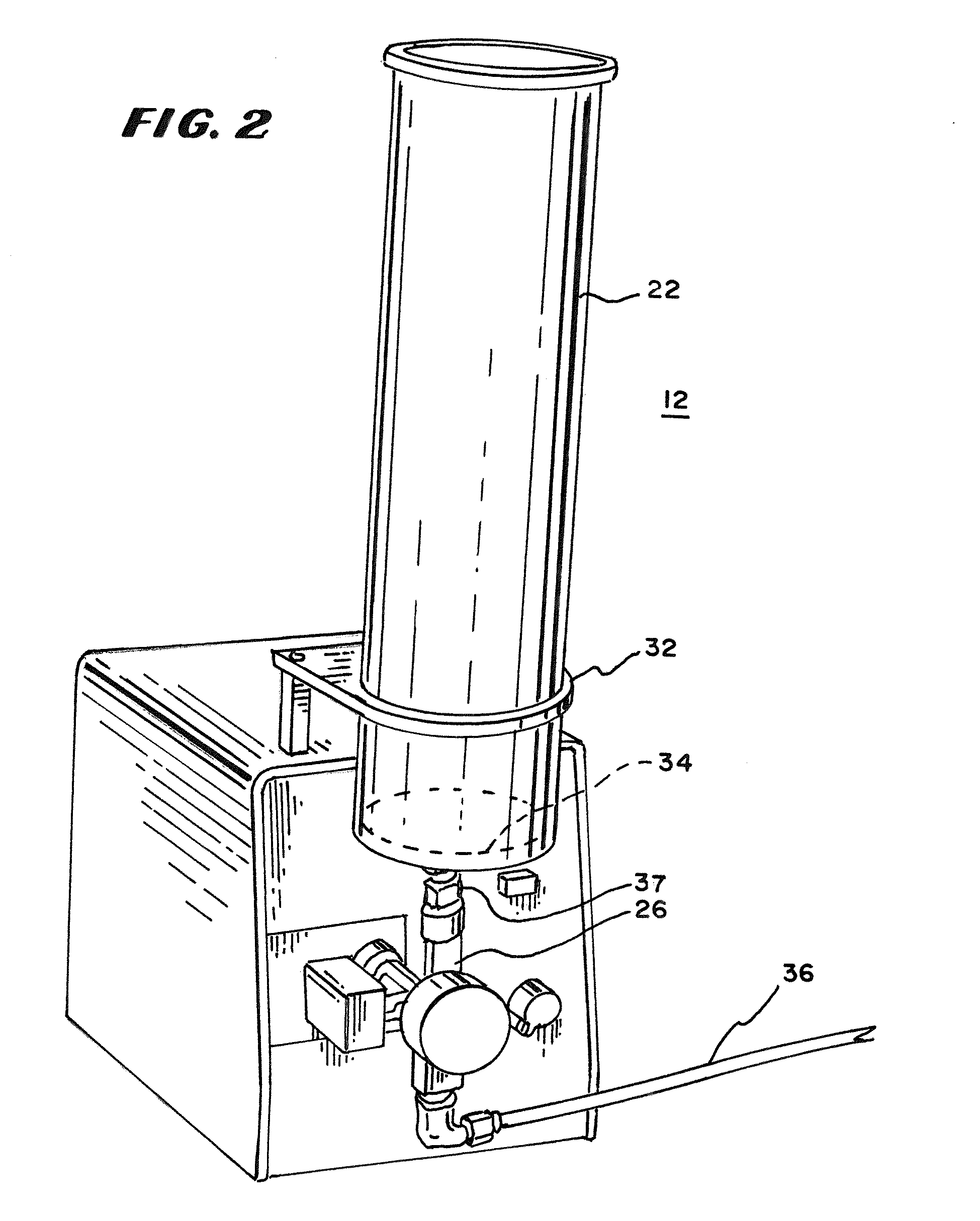
[0021]In FIG. 1 there is shown a preparatory liquid chromatographic system 10 having a controller and solvent system 14, a column and sample injection system 12, downstream components including the detector, readout recorder and fraction collector 16, waste collection apparatus 18 and a purge gas source 20. The column and sample injection system 12 includes a directly connected sample container 22, a container-pump connector 24, a sample injection pump 26, a sample injection valve 28 and the column 30. The directly connected sample container 22 communicates through a container-pump connector 24 with the inlet of a column 30 either directly or through a sample injection valve 28. If a sample injection valve is included rather than a direct connection to the inlet of a column, the inlet of the column communicates with one port of the sample injection valve, the solvent system with another, a waste system with still another and a purge gas source with still another. A valve connected i...


PUM

PropertyMeasurementUnit
suctionaaaaaaaaaa
sizeaaaaaaaaaa
solventaaaaaaaaaa

Abstract

A sample injection apparatus includes a sample container and a tube that communicates with the inlet of a liquid chromatographic column. The sample container receives at least a preparatory-sized sample. A syringe pump pulls sample from the sample container and applies it to the inlet of the liquid chromatographic column.

Description

RELATED CASES[0001]This application is a continuation of U.S. provisional application 61 / 373,602 filed Aug. 13, 2010, by inventor, Dale A. Davison. The benefit of provisional patent application 61 / 373,602 is claimed.BACKGROUND OF THE INVENTION[0002]This invention relates to sample injection into liquid chromatographs.[0003]It is known to transfer large samples in preparatory liquid chromatography from a flask or other container into a liquid chromatographic column for preparatory liquid chromatography. One prior art method of transferring the sample to the column is to prepare the sample in a flask or other container and then pipette the sample into the column. The method is slow and under some circumstances fails to transfer the entire sample. Instead, some of the sample remains in the flask because it is difficult to get it into the pipette. In another prior art method, the sample is pumped from a container near the column through tubing inserted into the open top of the container...

Claims


Application Information

Patent Timeline
Patent Type & Authority Applications(United States)
IPC IPC(8): G01N30/84
CPCB01D15/14G01N30/16G01N2030/167G01N30/20G01N30/18
Inventor DAVISON, DALE A.
Owner TELEDYNE INSTR INC
Learn More