Photovoltaic Shingle

a photovoltaic and shingle technology, applied in the field of photovoltaic modules, can solve the problems of heavy conventional photovoltaic panels, unaesthetically pleasing photovoltaic panels, and inconvenient viewing

Inactive Publication Date: 2012-08-16
PETERSON GEORGE D +1
View PDF7 Cites 40 Cited by
  • Summary
  • Abstract
  • Description
  • Claims
  • Application Information

AI Technical Summary

Benefits of technology

[0011]The present photovoltaic shingles can be installed using conventional roofing tools and by traditional roofing companies with only minimal instruction on how to lay the photovoltaic shingles on a roo

Problems solved by technology

One disadvantage with conventional photovoltaic panels are that they are seen by some as not being aesthetically pleasing to view.
A second disadvantage is that conventional photovoltaic panels are heavy, due in part to the weight of the glass superstrate.
For example, current building integrated photovoltaic (BIPV) roofing systems are considered by most to have poor aesthetics and are expensive and difficult to install, repair and upgrade.
Further, since BIPV roofing systems are installed over existing roofing shingles, it i

Method used


Image

  • Photovoltaic Shingle
  • Photovoltaic Shingle
  • Photovoltaic Shingle

Examples


Embodiment Construction

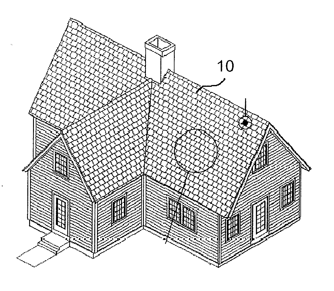
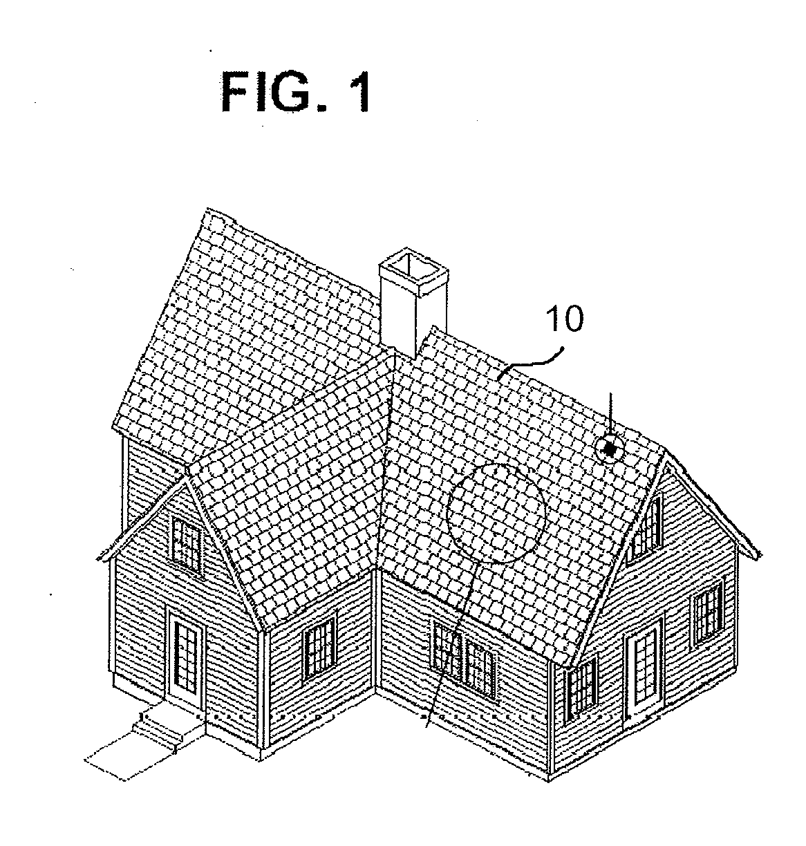
[0022]The present photovoltaic cell will now be described with reference to the drawings. FIG. 1 shows a exemplary structure which has a roof covered with photovoltaic shingles 10. As will be discussed further below, the shingles 10 include an integrated photovoltaic module. The individual photovoltaic shingles are connected together to form an array of photovoltaic shingles which, when installed, mimic the look of conventional shingles.

[0023]Solar energy is collected by encapsulated photovoltaic cells in the photovoltaic shingles 10 and converted into direct electric current (“DC current”). The photovoltaic cells are connected together on a single, three, or six, tab shingle to combine the solar energy delivered to the exposed surface of the shingle. The DC current is transferred to a junction by two electrical wires. In the junction, these wires are further sealed and insulated through encapsulation and connected to two output electrical wires. The output electrical wires are conn...


PUM


Abstract

A photovoltaic shingle integrates a photovoltaic assembly within a roofing shingle. The shingle includes a first encapsulating material layer disposed on a substrate followed by the photovoltaic cell assembly and a second encapsulating material layer disposed on the photovoltaic assembly. A transparent superstrate such as a resin with polymer film is formed on the second encapsulating material layer. In one advantageous form, the photovoltaic shingle has at least two channels formed completely through the shingle in a stacking direction of the respective layers but only partially through in a direction perpendicular to the stacking direction thereby defining at least two tabs. In alternative forms, there may be additional channels such as but not limited to, two channels defining three tabs or five channels defining six tabs. The photovoltaic shingles may be arranged in an array to form a primary waterproof layer of a suitably pitched roof structure.

Description

CROSS REFERENCE TO RELATED APPLICATIONS[0001]This application claims benefit of U.S. Provisional Application No. 61 / 402,820, filed Sep. 7, 2010 (which is hereby incorporated by reference). This application also relates to U.S. patent application Ser. No. 13 / 220,085, filed on Aug. 29, 2011; which claims the benefit of U.S. Provisional Application No. 61 / 402,233, both herein incorporated by reference.FIELD OF THE INVENTION[0002]The present invention relates to a photovoltaic module and in particular a photovoltaic module incorporated into a photovoltaic shingle.BACKGROUND OF THE INVENTION[0003]Electrical solar energy production is conventionally produced using photovoltaic cells. Typically the photovoltaic cells are arranged in an assembly which includes several photovoltaic cells. The assembly of photovoltaic cells are incorporated into a module. The modules, each comprising a number of photovoltaic cells, are joined together to form an array of photovoltaic modules. The photovoltaic...

Claims


Application Information

Patent Timeline
IPC IPC(8): H01L31/042H01L31/0203
CPCY02B10/12H02S20/25H01L31/048Y02E10/50H01L31/044Y02B10/10
Inventor PETERSON, GEORGE D.BENNETT, ROBERT
Owner PETERSON GEORGE D
Why Eureka
Try Eureka