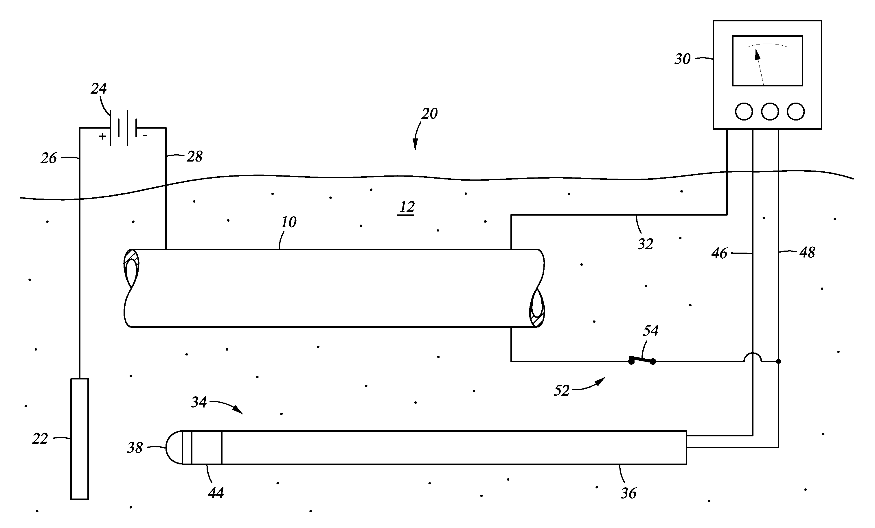
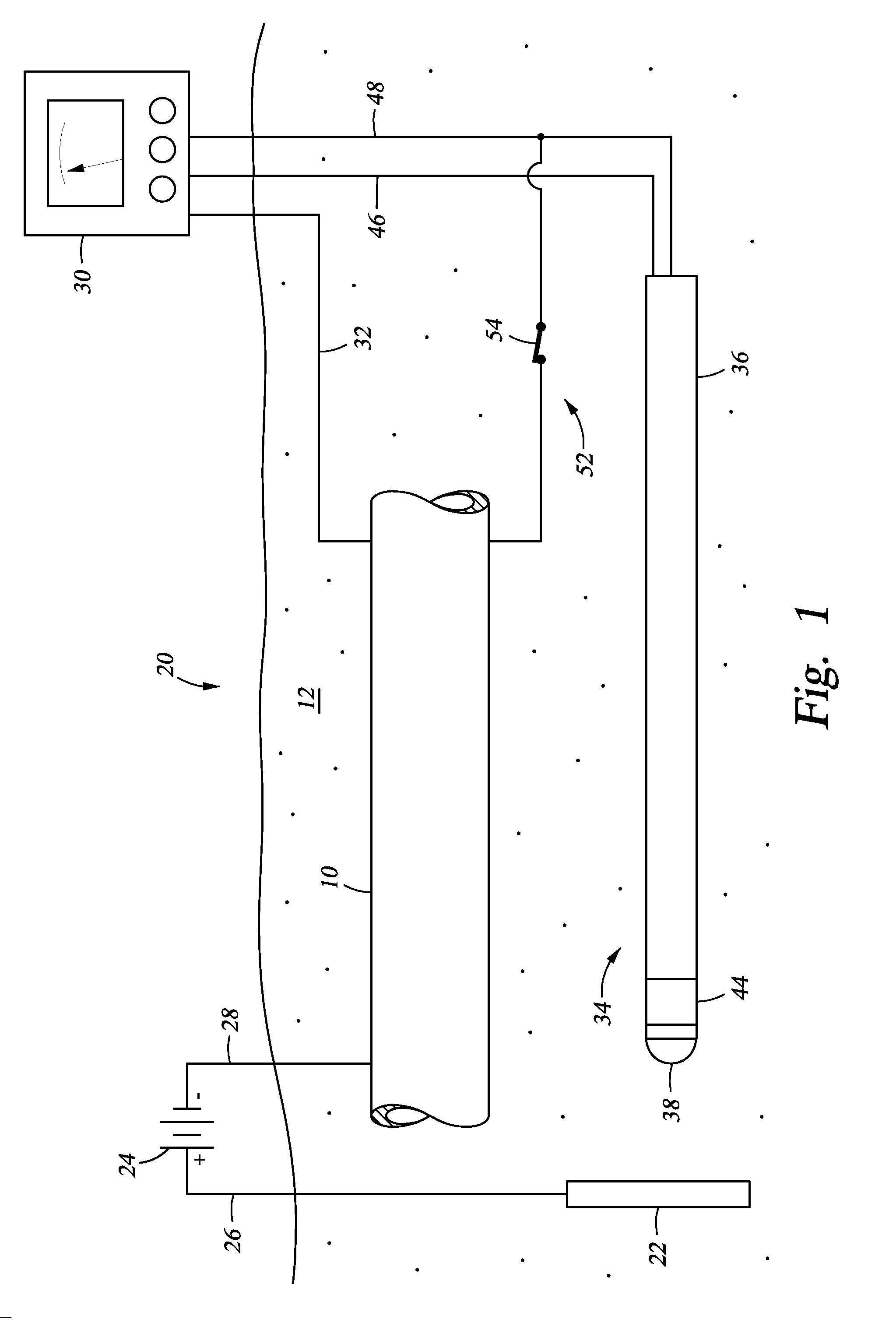
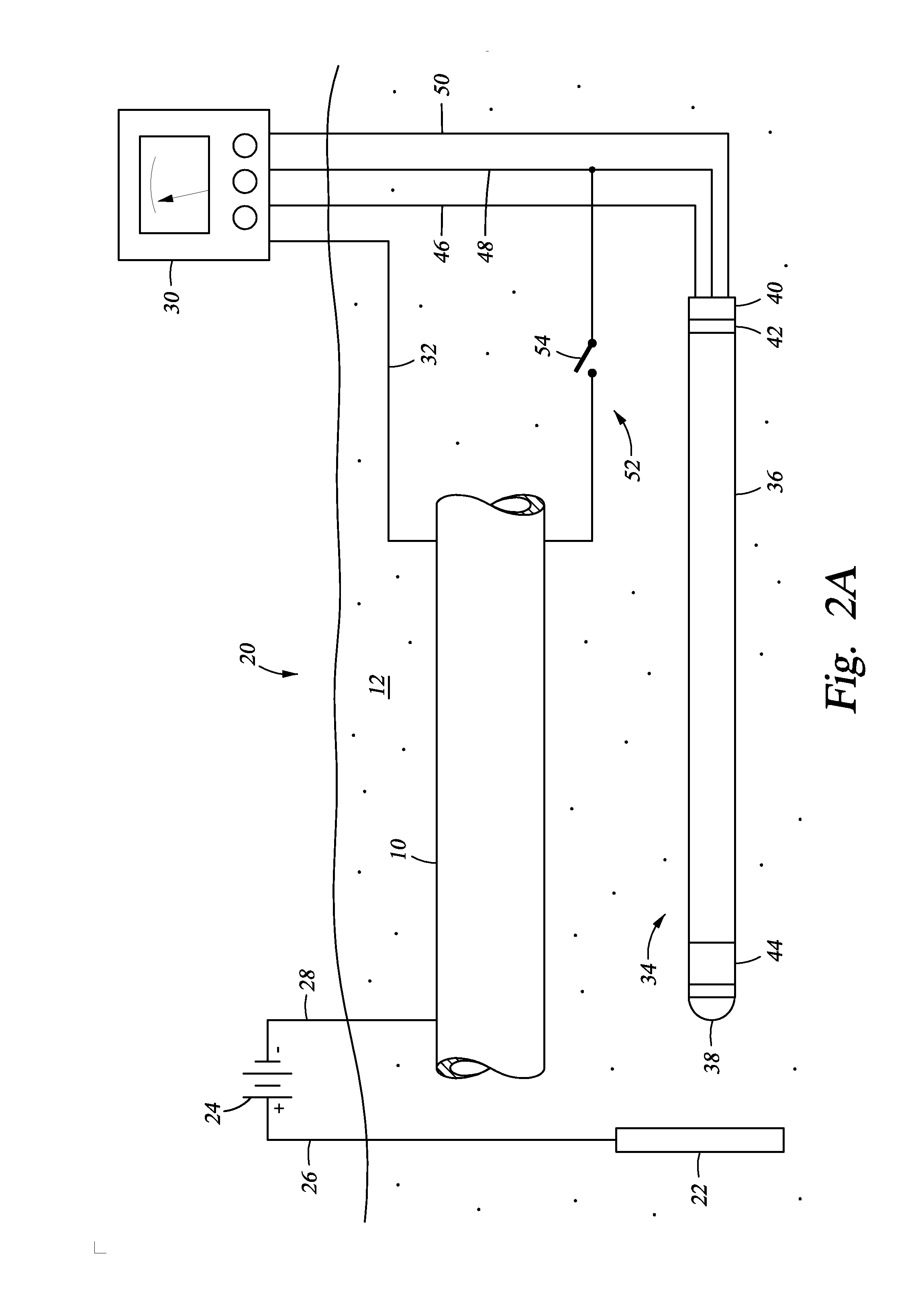
[0007]The present disclosure discloses a method and apparatus for monitoring and assessing cathodic protection of an object within a medium. In an example, disclosed herein is a system for measuring cathodic protection of a protected object submerged in a medium and protected by an impressed current and an energized anode submerged in the medium. In one embodiment the system is made up of a segmented probe. In an example embodiment, the probe has first, second, and third segments. One of the first or third segments is in selective electrical communication with the protected object. When one of the first and third segments are in electrical communication with the protected object, the first and third segments are electrically isolated by the second segment and a cathodic protection current is impressed onto the protected object. Measuring polarization between the first and third segments substantially reflects the polarization of the protected object without any IR error. In another embodiment, fourth and fifth segments are included, where the fourth segment is a galvanically corroding connection between the fifth and third segments. The galvanically corroding connection of the fourth segment can include a material with a galvanically noble value, so that when the probe is set in a galvanically non-corrosive medium the electrical communication between the fifth and third segment is maintained through the galvanically corroding connection; additionally when the probe is set in a galvanically corrosive medium the galvanically corroding connection galvanically corrodes and the fifth segment is electrically isolated from the third segment. A multi-meter can be included with the system that is in electrical communication with the protected object and the electrically conducting segments. The first segment can be fabricated in a geometry that has been used in the lab to establish cathodic disbondment characteristics for a variety of representative coatings in a variety of representative electrolytes. The coated lab samples can be prepared with an engineered flaw that is of the same geometry as the first segment. The system can include a power supply for providing the impressed current. Alternatively, a controller is included with the system that is in communication with the power supply, the first segment, and the second segment. The electrical connection between the protected object and one of the first or second segments can be made up of an electrically conducting member and an on off switch in the electrically conducting member. The protected object can be a pipeline, a tank, a structure, a reinforcing bar, or a vessel. The medium can be soil, sand, rock, clay, water, a cementitious material, or combinations thereof. Also described herein is a method and apparatus for monitoring and assessing corrosion and cathodic protection of an object within an electrolyte and can also be used to measure electrolyte resistivity and galvanic corrosivity (qualitatively).
[0008]Also described herein is a cathodic protection system for cathodically protecting a metallic object that contacts a medium. In this embodiment the cathodic protection system includes a power source coupled to the metallic object, so that when the power source is energized current is impressed onto the metallic object. In an embodiment, an anode is connected to the power source and contacting the medium. In an embodiment, a probe is included that contacts the medium and made up of a first segment that is physically connected to the third segment but electrically isolated by a nonmetallic second segment. The first and third segments are selectively disconnectable from each other and the object through wires terminated above ground. Optionally included is a multi-meter coupled to the metallic object, the first segment, and the second segment. Further optionally included is a controller connected to the multi-meter and the power source, so that when the multi-meter measures polarization values between the second segment and the metallic object that are outside of a predetermined range, the controller can adjust the power supply to change the level of cathodic protection. In an example, the predetermined range of polarization indicates a desired level of cathodic protection. In an embodiment, a third segment is included with the probe that is electrically isolated from the first and second segments. Electrical connection between the protected object and one of the segments can be a conducting member with an included on / off switch. The metallic object can be a pipeline, a tank, a structure, a reinforcing bar, or a vessel. The medium can be soil, sand, rock, clay, water, a cementitious material, or combinations thereof.
[0009]Yet further disclosed herein is a method of monitoring cathodic protection of a metallic object that contacts a medium. In an example, the method can include providing a probe having a first segment (metallic) and a third segment (metallic) separated by a second segment (nonmetallic) and contacting the probe with the corrosive medium. The third segment and the metallic object can be connected while impressing an electrical current to the metallic object. The electrical connection between the third segment and the metallic object can be interrupted and the voltage difference between the first segment and the third segment measured. This is representative of the polarization magnitude on the metallic object resulting from the active cathodic protection system. Based on the estimated polarization, the amount of cathodic protection provided to the metallic object can be assessed. The amount of electrical current being impressed onto the metallic object an be adjusted to ensure a proper amount of cathodic protection is being supplied. In an example embodiment, the first segment of the probe has been designed to represent a coating holiday on the pipe. In areas where overprotection is a concern, the roles of the first segment and third segment are reversed. Under normal operation, the first segment is normally connected to the object and the third section is only connected long enough to achieve stable polarization chemistry on its surface. The magnitude of polarization measured between the first and third segments with the first segment momentarily disconnected can now be compared to laboratory data to determine if the potentials may cause coating degradation. In an alternative, the step of providing electrical connection between the first segment and the metallic object, and the third segment and the metallic object will involve connecting a conductive member (wires) where the connections have selectively open and closed switches. The electrical connection between the first segment and the metallic object can be interrupted by opening the switch. The electrical connection between the third segment and the metallic object can also be interrupted by opening that switch.

