Induction furnace for melting of metals, lining for an induction furnace and method for production of such lining.

a technology of induction furnace and metal melting, which is applied in the direction of furnace components, lighting and heating apparatus, household objects, etc., can solve the problems of graphite lining, graphite lining, induction coil and cooling system of lining subject to high thermal stress, etc., and achieves improved energy utilization, easy exchange, and high electrical conductivity

Inactive Publication Date: 2012-08-16
ELKEM CARBON
View PDF1 Cites 2 Cited by
  • Summary
  • Abstract
  • Description
  • Claims
  • Application Information

AI Technical Summary

Benefits of technology

[0009]The lining can be in the form of a self-sustaining crucible that can be exchanged very easily.
[0010]When using the induction furnace according to the present invention for melting of metals having a low electrical conductivity which do not connect inductively in solid state, such as silicon and germanium, the lining in the induction furnace at the start of a melting cycle when the furnace at the start is filled with solid metal, will connect inductively and thereby be heated. The solid metal in the furnace will thereby be heated by radiation from the lining. When part of the metal has melted the molten metal which has a far higher electrical conductivity than the solid metal, will connect inductively and the heat energy will be supplied directly to the molten metal. Thus the lining will only be subjected to very high temperature at the start of each melting cycle. A far better energy utilization will thereby be achieved as the heat energy is transferred directly to the molten metal in the furnace and consequently the heat stress on the lining will be substantially reduced. The need for cooling of the lining and of other parts of the furnace will thus also be reduced. This results in a substantially increased lifetime of the lining.
[0011]The lining according to the present invention further has the advantage that it can be made from very clean materials. For example, ball clay, bentonite, and other clays must be excluded from the lining of the present invention. Silica and alumina may be included in amounts of up to about 5% by weight. Graphite fibers can be in the mixture of the present invention which may have a length of between about 3 mm to about 12 mm. When graphite fibers are included, the amount of graphite particles in the mix should be reduced in order to keep the total graphite content constant.
[0019]When the carbon-based binder is added to the mixture of graphite particles and silicon carbide particles, this will provide a good strength at low temperatures. During heating and baking the binder will carbonize and form a solid carbon. In addition the use of carbon-based binder results in a more dense lining which prevents penetration of molten metal into the lining.

Problems solved by technology

This has disadvantages as the graphite lining during the whole melting period will be the hottest part of the induction furnace.
This requires a very comprehensive cooling of the graphite lining causing high heat losses.
Further the graphite lining, the induction coil and the cooling system for the lining will be subjected to high thermal stress.

Method used


Image

  • Induction furnace for melting of metals, lining for an induction furnace and method for production of such lining.
  • Induction furnace for melting of metals, lining for an induction furnace and method for production of such lining.
  • Induction furnace for melting of metals, lining for an induction furnace and method for production of such lining.

Examples


example 1

Production of Lining in Furnace

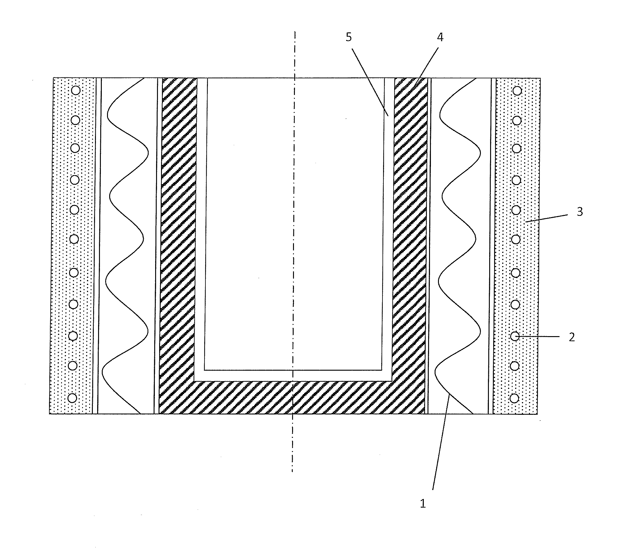
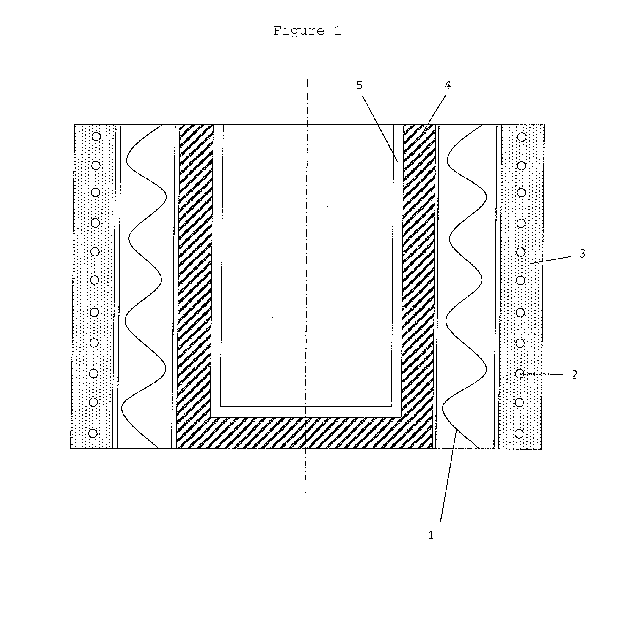
[0070]A lining for a 75 kW induction furnace operating at a frequency of 3000 Hz was produced as follows: On the inside of the refracting layer 3 with the embedded coil 2 (FIG. 1) an insulating refractory layer 1 was cast. The insulating refractory layer 1 consisted of 96% by weight of Al2O3, the remaining being impurities such as SiO2, CaO and FeO. The thickness of the insulating refractory layer 1 was 25 mm. On the inside of the insulating refractory 1 it was tamped a lining 4 consisting of a powder mixture of 40% by weight graphite powder, 49% by weight silicon carbide and 11% by weight of silicon particles. To this mixture it was added 14.3% phenol formaldehyde resin binder based on the weight of the mixture of graphite particles, silicon carbide particles and silicon particles. To the binder it was added hexamin as a curing agent. The lining was thereafter cured and baked by placing a susceptor in a form of a graphite cylinder in the center of the...

example 2

Production of Lining Outside of Induction Furnace

[0071]The lining 4 can alternatively be made separately outside the induction furnace by tamping the lining 4 between outer and inner mould parts. After tamping, the inner mould part is removed whereafter the lining is cured. The outer mould part is thereafter removed and the cured lining is placed in a suitable furnace or heating reactor where it is baked at temperature of above 1100° C. FIG. 4 shows this embodiment providing a piston 6 used for tamping the lining 4, an inner mould part 5, and coil 7 of a furnace or heating reactor 8. The method for coating the inside of the furnace with the mixture and forming the green liner with the inner mould part 5 and piston 6 is done in a conventional manner using conventional equipment. After the lining is removed from the furnace or heating reactor 8, it is placed in the induction furnace.

example 3

[0072]The lining of Example 1 was tested for inductivity at 1000° C. At start of the supply of electric energy to the induction coil 2 the furnace took maximum effect of 75 kW at once. Thereafter solid silicon was supplied to the furnace and melted. After melting and pouring of the silicon from the furnace, the lining was allowed to be cooled to 200° C. and again tested for inductivity at maximum effect of 75 kW. The lining then took 65 kW. The effect taken by the lining was thus reduced by 15%. This shows that during curing and baking of the lining the conductivity of the lining is increased such that it connects inductively.


PUM

PropertyMeasurementUnit
temperatureaaaaaaaaaa
lengthaaaaaaaaaa
particle sizeaaaaaaaaaa

Abstract

The present invention relates to an induction furnace for melting of metals that do not connect inductively in solid state. The induction furnace has a lining comprising a mixture of graphite and silicon carbide and has an electric conductivity higher than the electrical conductivity of the metal to be melted when metal is in solid state, but lower than the electrical conductivity of the metal to be melted when the metal is in molten state. The invention further relates to a lining for induction furnace and to a method for producing such lining.

Description

CROSS-REFERENCE TO RELATED APPLICATION[0001]This application is a Divisional Application of U.S. patent application Ser. No. 13 / 090,734 filed Apr. 20, 2011, which in turn was a Continuation In Part of International application PCT / NO2009 / 000364 filed Oct. 19, 2009, which in turn claims the benefit of priority from NO 20084613 filed Oct. 31, 2008, the contents of each of these applications are incorporated herein by reference.TECHNICAL FIELD[0002]The present invention relates to an induction furnace for melting of metals, particularly silicon, and more particularly to a lining for such furnace.TECHNICAL BACKGROUND[0003]By melting of metals in induction furnaces most metals have such high electrical conductivity that they connect inductively in solid state. For melting of such metals in induction furnaces the electrical properties of the lining in the induction furnace is not important and the lining can be made from electric isolating materials. Metals having a low electrical conduct...

Claims


Application Information

Patent Timeline
Patent Type & Authority Applications(United States)
IPC IPC(8): F27D1/16
CPCH05B6/24C04B2235/725F27B14/061F27D1/0006C04B35/101C04B35/522C04B35/532C04B35/573C04B35/66C04B2235/3208C04B2235/3272C04B2235/3418C04B2235/3826C04B2235/425C04B2235/428C04B2235/72C04B35/565
Inventor EGELAND, BJORNH BERG, ALFMADSHUS, STIANJOHANSEN, JOHAN ARNOLD
Owner ELKEM CARBON
Why Eureka
Try Eureka