Springless combination shock absorber and suspension apparatus, and method of use

a shock absorber and suspension device technology, applied in the field of vehicle shock absorbers, can solve the problems of device not supporting the weight of the vehicle, device lacks adjustment control, device is effectively non-load bearing, etc., to reduce the impact shock, dampen the shock impulse, and smooth out or damp the shock impulse

Active Publication Date: 2012-08-16
ELITE SUSPENSION SYST
View PDF13 Cites 24 Cited by
  • Summary
  • Abstract
  • Description
  • Claims
  • Application Information

AI Technical Summary

Benefits of technology

[0030]When the shock absorber is compressed by impact forces, the floating piston moves toward the top eyelet, thereby compressing the nitrogen gas in the first fluid chamber and dampening the shock of the impact by controlling oil flow through the valve(s). When the shock absorber relaxes after remo

Problems solved by technology

However, the load is only partially sustained by the compressed gas therewithin and thus the device is effectively non-load-bearing without a spring working in concert.
Further, this device does not support the vehicle's weight.
However, this device lacks adjustment control, although it does provide springless operation.
However, no biasing effect is crea

Method used


Image

  • Springless combination shock absorber and suspension apparatus, and method of use
  • Springless combination shock absorber and suspension apparatus, and method of use
  • Springless combination shock absorber and suspension apparatus, and method of use

Examples


example i

Process

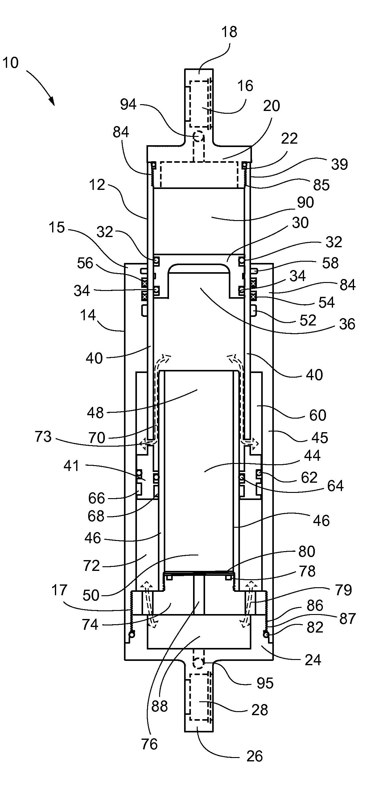
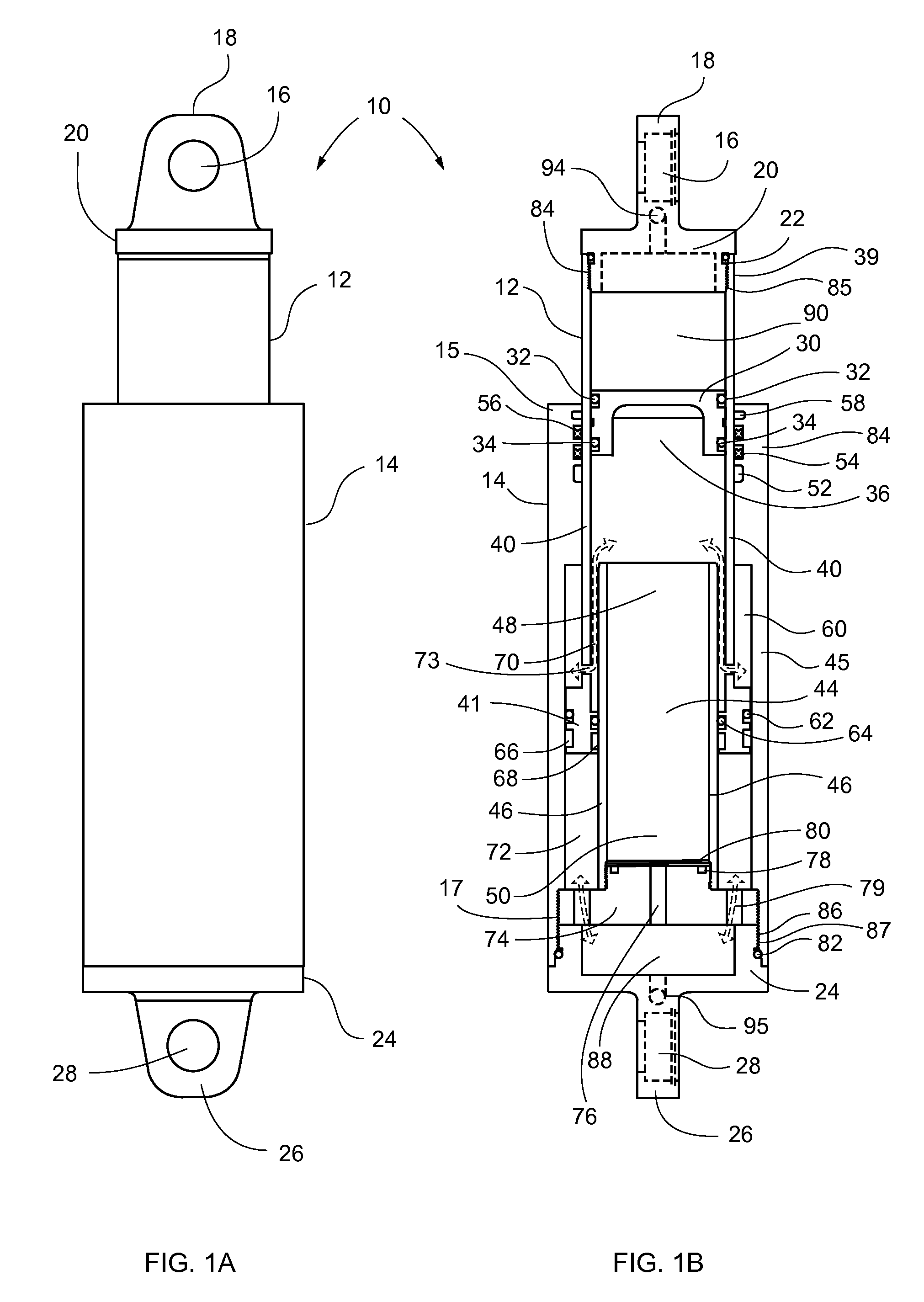
[0100]Shock absorber 10 is first fully extended (inner tube 12 pulled all the way out) and floating piston 30 is set at its lowest position (just above piston tube holes 43). Shock absorber 10 is then filled with oil in all chambers below floating piston 30. First fluid chamber 90 is subsequently filled with nitrogen at an initial pressure (Pi). Shock absorber 10 is now pressurized. When an external force is applied (such as the weight of a vehicle) it will produce pressure (Pv) in second fluid chamber 36 below piston ring 41 which will act against first fluid chamber 90 pressure. This pressure differential (dP=Pv−Pi) will cause the inner tube 12 to move downwards. By doing so, oil is displaced against floating piston 30 causing it to move upwards, which in turn causes the pressure in the first fluid chamber 90 to increase. Inner tube 12 eventually stops when the pressure in first fluid chamber 90 equals the pressure in the second fluid chamber 36. The vehicle settles at a gi...


PUM


Abstract

A springless combination shock absorber and suspension apparatus comprising three tubes: An outer tube, a piston tube (inner tube) and a stationary (damping) tube, with a floating piston disposed in the inner piston tube, wherein the floating piston forms two chambers therein, a lower liquid chamber and an upper gas chamber. Fluid dampens shocks by passing through a two-way valve in the outer tube and may be controlled internally by a shim plate positioned over apertures or valve passageways, or, in a separate embodiment, by external adjustment of flow by rotating adjusting plates to open and close the valve passageways. The amount by which the gas chamber is reduced in compression is large enough to generate the high pressures required to produce spring-like forces. This design allows the gas pressure chamber to operate effectively as a spring.

Description

CROSS-REFERENCE TO RELATED APPLICATIONS[0001]NoneFEDERALLY SPONSORED RESEARCH OR DEVELOPMENT[0002]NonePARTIES TO A JOINT RESEARCH AGREEMENT[0003]NoneREFERENCE TO A SEQUENCE LISTING[0004]NoneBACKGROUND OF THE INVENTION[0005]1. Technical Field of the Invention[0006]The present invention relates generally to shock absorbers for vehicles, and more specifically to an adjustable shock absorber that does not require a spring to support a vehicle.[0007]2. Description of Related Art[0008]A shock absorber or damper is a mechanical device designed to smooth out or damp shock impulse, and dissipate kinetic energy. Most shock absorbers (dampers) are utilized with external springs (coils).[0009]Various devices for absorbing shock for vehicles have been attempted utilizing a piston rod moving up and down in a cylinder to provide oscillation dampening (“twin-tube” configuration) therewithin to provide smoothing of shocks that would otherwise be passed to the vehicle. Other shock absorbers utilize a...

Claims


Application Information

Patent Timeline
IPC IPC(8): B60G15/12F16F9/06F16F9/34
CPCB60G15/12F16F9/063F16F9/44F16F9/3242
Inventor ALLEN, MARK M.GIANNOPOULOS, NICHOLAS C.
Owner ELITE SUSPENSION SYST
Why Eureka
Try Eureka