Rolling bearing

a technology of contact bearings and rolling bearings, which is applied in the direction of bearings, shafts and bearings, rotary machine parts, etc., can solve the problems of circumferential gaps and retardation of rotation, and achieve the effects of reducing cost, avoiding fretting, and being convenient to mov

Active Publication Date: 2012-08-16
NTN CORP
View PDF5 Cites 7 Cited by
  • Summary
  • Abstract
  • Description
  • Claims
  • Application Information

AI Technical Summary

Benefits of technology

[0028]The cage for the roller bearing assembly according to the present invention may include two or more arcuate members each having a plurality of pockets defined therein for accommodating a corresponding number of rollers, and a retention ring for non-separably connecting together the arcuate members juxtaposed in a ring form in a circumferential direction over the entire circumference of the cage. According to the construction described above, assemblage is easy to accomplish and requires a reduced cost, and the cage can function as the split type assuredly without relying on the operating condition, thereby avoiding the fretting.

Problems solved by technology

In a condition in which the cage has been assembled onto a shaft, the respective arcuate members, even though no circumferential gap is formed at the joints between the respective arcuate members, move in a direction away from each other by the effect of the centrifugal force when rotated, and as a result, the circumferential gaps result in.
Also, when the arcuate members shift into a loaded region, the radial gap changes from positive to zero and, therefore, the rollers accommodated within the corresponding pockets in the arcuate members will be braked, resulting in retardation of the rotation.

Method used


Image

  • Rolling bearing
  • Rolling bearing
  • Rolling bearing

Examples


Embodiment Construction

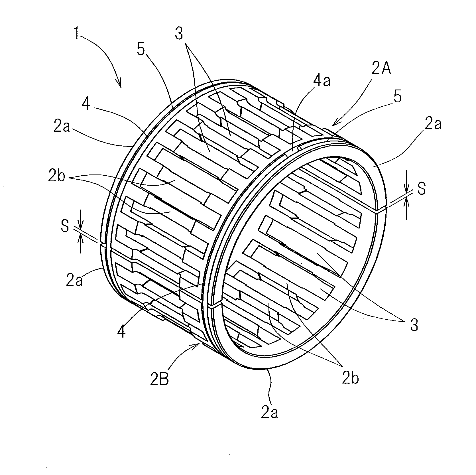
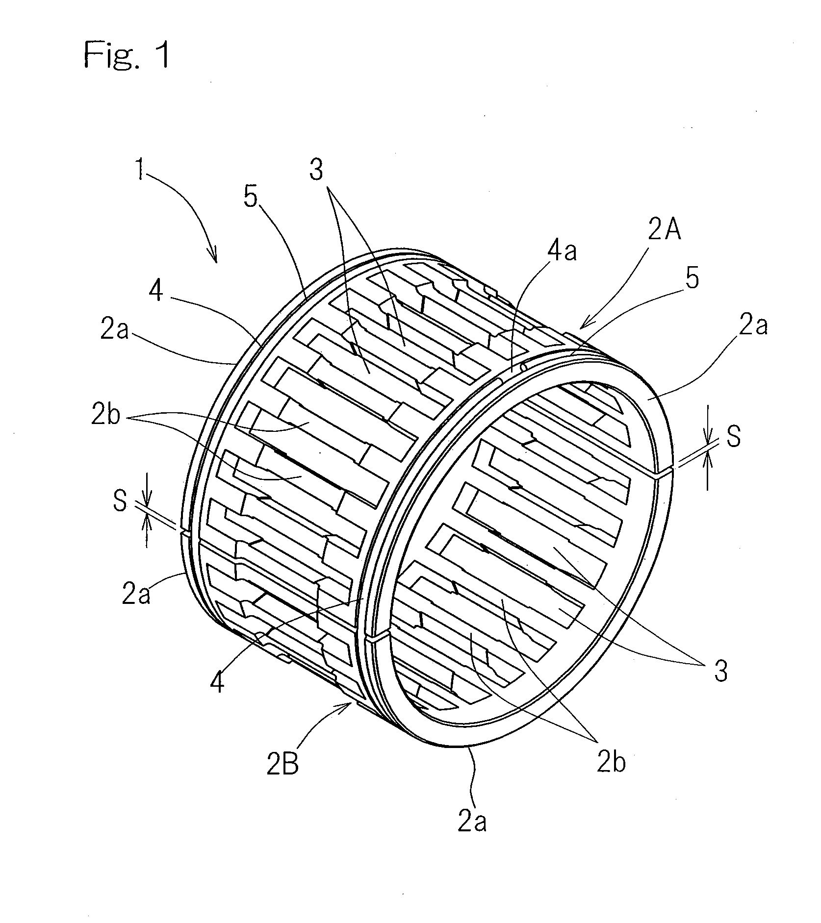
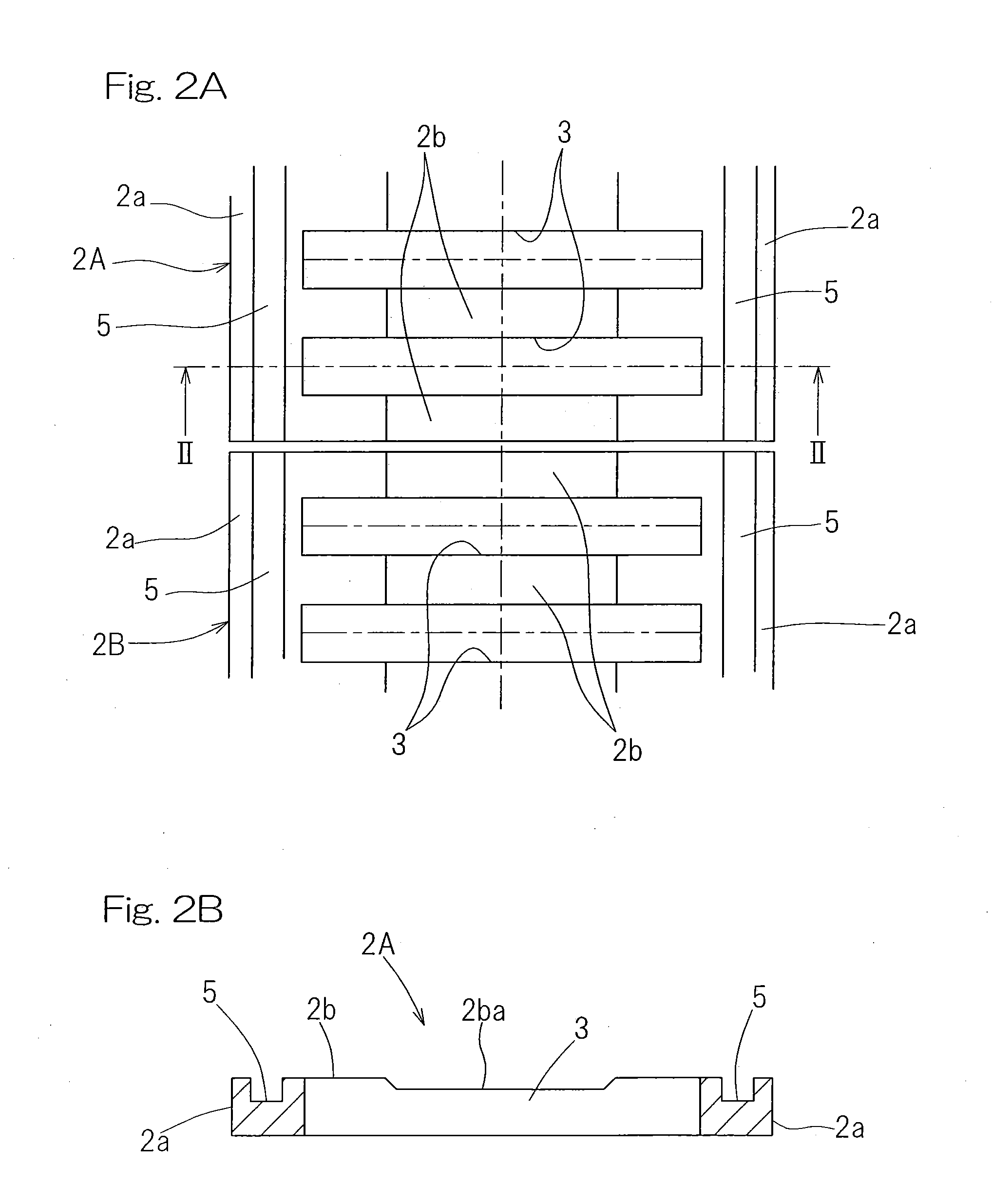
[0042]One preferred embodiment of the present invention will now be described in detail with particular reference to FIGS. 1 to 11. A retainer or cage 1 employed in a rolling contact bearing assembly is of a type comprised of two first and second arcuate members 2A and 2B connected together so as to assume a ring shaped configuration. More specifically, each of the first and second arcuate members 2A and 2B has a curved or convexed outer surface, or an outer arc surface, and a curved or concaved inner surface, or an inner arc surface opposite to the outer arc surface, and also has first and second side edges opposite to each other. The first and second arcuate members 2A and 2B so shaped as described above have respective groups of roller pockets 3 defined therein for accommodating a corresponding number of rollers and are positioned one above the other so as to assume the ring shaped configuration with the first and second opposite side edges of one of the first and second arcuate ...


PUM


Abstract

Two or more arcuate members (2A, 2B), each having a plurality of pockets (3) defined therein for accommodating corresponding rollers, are placed one above the other to form a ring shaped assembly and are subsequently connected non-separably together by means of a retention ring (4) to thereby complete the cage (1). The arcuate members (2A, 2B) are so connected together that its inner periphery may assume a position radially inwardly of the outer diameter of a shaft such that in a condition having been assembled onto the shaft, they can displace in a direction radially outwardly against an elastic compressive force of the retention ring (4) to invite a circumferential gap (S) at each joint between the arcuate members (2A, 2B).

Description

CROSS REFERENCE TO THE RELATED APPLICATION[0001]This application is based on and claims Convention priority to Japanese patent application No. 2009-239376, filed Oct. 16, 2009, the entire disclosure of which is herein incorporated by reference as a part of this application.BACKGROUND OF THE INVENTION[0002]1. Field of the Invention[0003]The present invention relates to a rolling contact bearing assembly utilizing a plurality of rollers and a cage, or a roller bearing, and, more particularly, to an improvement of the cage designed to avoid the occurrence of fretting and generation of obnoxious noises during the operation of the roller bearing.[0004]2. Description of Related Art[0005]It is well known in the art that a cage equipped needle roller bearing is currently largely employed not only in automotive vehicles, but also in various industrial machines and equipments because it has light weight and compact features. For example, a transmission for use in an automotive vehicle makes u...

Claims


Application Information

Patent Timeline
Patent Type & Authority Applications(United States)
IPC IPC(8): F16C33/46
CPCF16C33/504F16C2208/00F16C43/04F16C2206/40F16C33/56F16C19/48F16C2361/61F16C33/4617
Inventor FUKAMI, RINOOISHI, SHINJINISHIKAWA, MAKOTONAKAGAWA, TSUTOMU
Owner NTN CORP
Why Eureka
Try Eureka