Cooling of a Gas Turbine Component Designed as a Rotor Disk or Turbine Blade

a technology of gas turbine components and turbine blades, applied in the direction of engine fuction, machine/engine, engine manufacturing, etc., can solve the problems of limiting the service life of the corresponding components, unable to achieve the desired calculated service life, and exchange of components, etc., and achieve the effect of prolonging the service li

Inactive Publication Date: 2012-08-16
SIEMENS AG
View PDF4 Cites 3 Cited by
  • Summary
  • Abstract
  • Description
  • Claims
  • Application Information

AI Technical Summary

Benefits of technology

[0008]The object of the invention is therefore the provisio...

Problems solved by technology

Regardless of the origin of the load, the increases may be impermissibly large, which limits the service life of the corresponding components.
Therefore, cracks can develop in the components referred to in the introduction, starting from the mouth region of the passages, which cracks have to be monitored and lead to exchange of the components when a critical crack length is exceed...

Method used


Image

  • Cooling of a Gas Turbine Component Designed as a Rotor Disk or Turbine Blade
  • Cooling of a Gas Turbine Component Designed as a Rotor Disk or Turbine Blade
  • Cooling of a Gas Turbine Component Designed as a Rotor Disk or Turbine Blade

Examples


Embodiment Construction

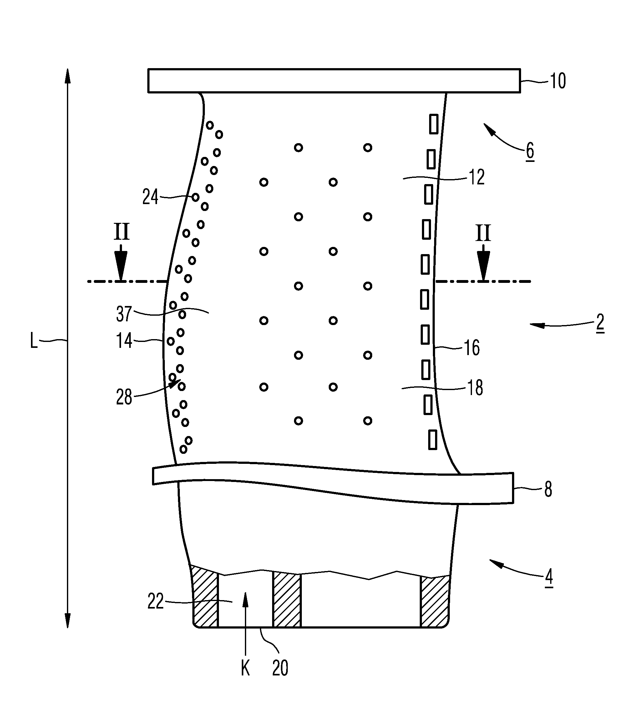
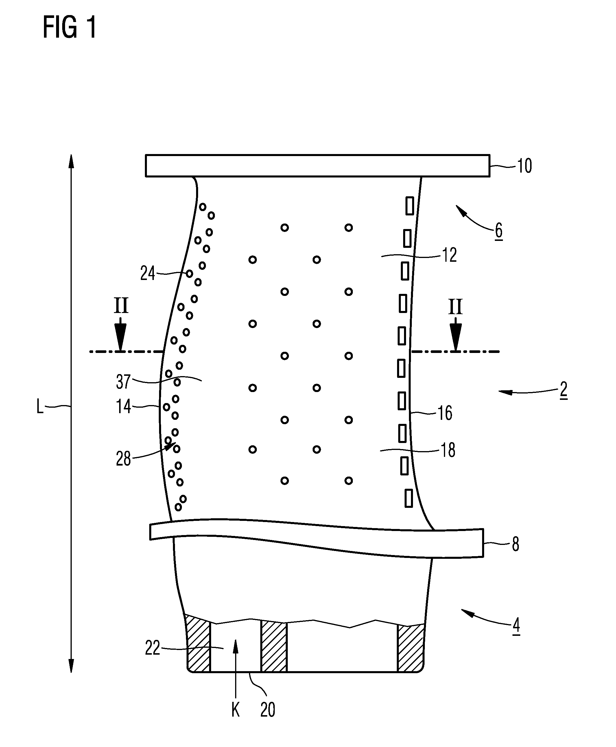
[0029]A turbine blade 2 according to FIG. 1 is designed as a stator blade for a gas turbine which is not additionally shown here. It comprises a root section 4 and a tip section 6 with associated platforms 8, 10, and a blade airfoil 12 in between these extending in the longitudinal direction L. The aerodynamically curved blade airfoil 12 has a leading edge 14 and a trailing edge 16, also extending essentially in the longitudinal direction L, with sidewalls 18 lying in between. The turbine blade 2 is fixed on the inner casing of the turbine via the root section 4, wherein the associated platform 8 forms a wall element which delimits the flow path of the hot gas in the gas turbine. The tip-side platform 10 lying opposite the turbine shaft forms a further limit for the flowing hot gas. The turbine blade 2 could alternatively also be designed as a rotor blade which in a similar way is fastened on a rotor disk of the turbine shaft via a root-side platform 8 which is also referred to as a...


PUM


Abstract

A gas turbine component for example a turbine blade or a rotor disk is provided. In order to extend the service life of the corresponding component by reducing the thermally or mechanically induced stress concentration in the direct surroundings of a duct opening onto a surface, at least one groove-like recess is provided near the effective zone of the opening.

Description

CROSS REFERENCE TO RELATED APPLICATIONS[0001]This application is the US National Stage of International Application No. PCT / EP2010 / 062880, filed Sep. 2, 2010 and claims the benefit thereof. The International Application claims the benefits of European Patent Office application No. 09011282.2 EP filed Sep. 2, 2009. All of the applications are incorporated by reference herein in their entirety.FIELD OF INVENTION[0002]The invention refers to a gas turbine component having at least one passage opening onto a smooth, i.e. unstructured, surface.BACKGROUND OF INVENTION[0003]A large number of generic-type gas turbine components are known from the prior art. A turbine blade, for example, with cooling air openings which open onto the surface of the turbine blade around which hot gas flows, as film-cooling holes, for example, may be understood by the gas turbine component which is referred to in the introduction. Also, a rotor disk for a gas turbine, in which mostly radially extending bores ar...

Claims


Application Information

Patent Timeline
IPC IPC(8): F01D5/18
CPCF01D5/081F01D5/085F05D2250/52F05D2260/94F05D2260/941F01D5/187
Inventor AHMAD, FATHIHOELL, HARALDKOLK, KARSTENNIMPTSCH, HARALDSETZ, WERNER
Owner SIEMENS AG
Why Eureka
Try Eureka