
Ear plug with surface electrodes

a technology of electrodes and ear plugs, applied in the field of ear plugs, can solve the problems of unattractive known systems, limited use and operation by qualified staff, and unattractive known systems, and achieve the effect of high quality

Active Publication Date: 2012-08-16
T&W ENG
View PDF14 Cites 54 Cited by
  • Summary
  • Abstract
  • Description
  • Claims
  • Application Information

AI Technical Summary

Benefits of technology

[0012]The present invention therefore aims at providing an ear plug by means of which ear plug electrical brain wave measurements such as EEGs become possible without or with a minimum of use of extensive and complicated equipment, which ear plug may be used in an uncomplicated way in everyday life while obtaining high quality brain wave signals, and with which the advantages related to the use of brain wave measurements may be readily utilized outside the laboratory.

Problems solved by technology

However, at least the signal processing devices of the known systems are, due to their complexity and use of extensive and complicated equipment, confined to use and operation by qualified staff.
Furthermore the placement of in by far most cases electrodes and in any case associated wiring on various parts of the subject's scalp and / or head renders the known systems rather unattractive for use outside laboratory surroundings, thus rendering exploitation of the advantages related to the use of brain wave measurements outside the laboratory, e.g in everyday use, rather cumbersome.
There is a risk of insufficient contacting between the ear canal and the electrodes due to the shell, which again may cause poor or insufficient signal quality.
Also, the shell properties imply a low durability of the proposed ear plug.
Furthermore, it is well known, that ear plugs of the type proposed in WO-A1-2007 / 047667 cause an enlarged risk of the user suffering from occlusion and / or insufficient ventilation of the ear canal, particularly during long term use.

Method used


Image

  • Ear plug with surface electrodes
  • Ear plug with surface electrodes
  • Ear plug with surface electrodes

Examples


Embodiment Construction

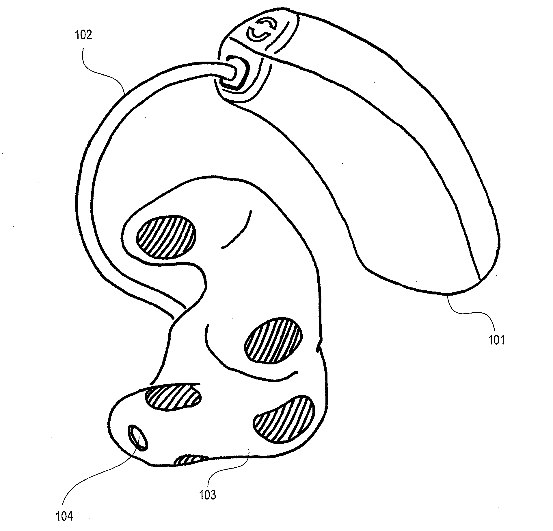
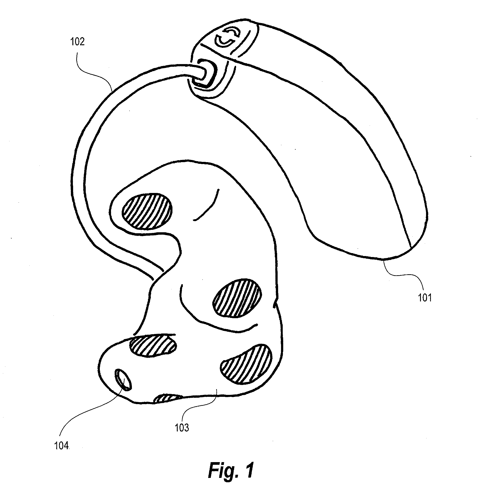
[0068]FIG. 1 shows an example of an ear plug according to the invention in a system with a behind-the-ear (BTE) component. The system comprises a BTE-component 101, an ear plug 103 according to the invention for insertion in the ear canal of a user, the ear plug 103 thus constituting an in-the-ear (ITE) component, and a connection means 102 for connecting the BTE-component 101 and the ear plug 103. The ear plug 103 comprises a surface and a connection opening 104. In one embodiment of the invention, this system could be a hearing aid.

[0069]The opening 104 is in one embodiment of the system an opening for a receiver of a hearing aid. The receiver is placed in an ear plug 103 in a so called receiver-in-the-ear (RITE) solution, connected to the BTE-component 101 through connecting means 102. In a variant the hearing aid receiver is be placed in the BTE-component and sound is transmitted to the user through connection 104 connected to the BTE-component via a sound tube 102. The connecti...


PUM

PropertyMeasurementUnit
Areaaaaaaaaaaa
Flexibilityaaaaaaaaaa
Shapeaaaaaaaaaa

Abstract

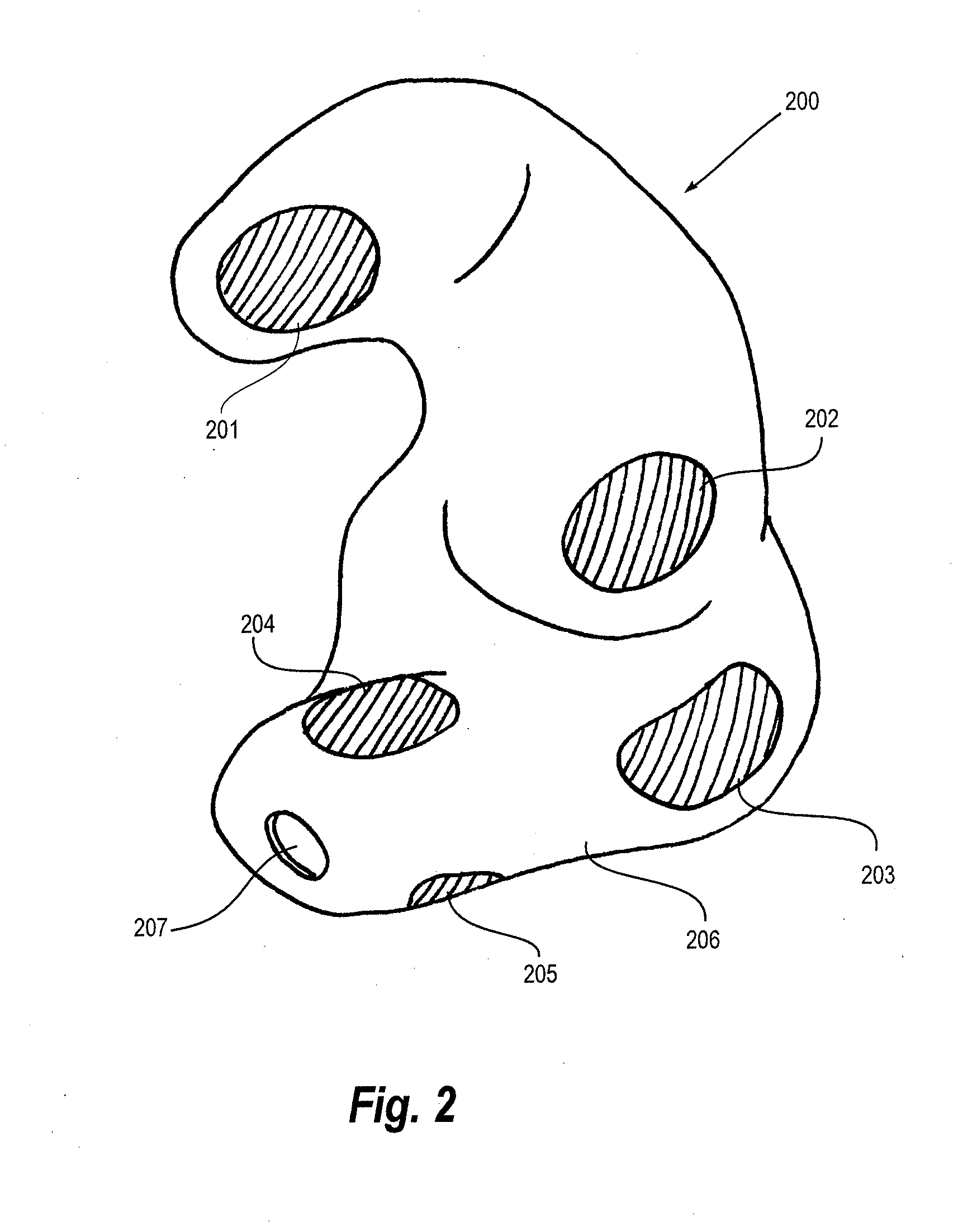
An ear plug (200) comprises a shell (206) with at least two electrodes (201-205) adapted for measuring brain wave signals, said electrodes (201-205) being connected with means for processing the measured signals, wherein the contours of the outer surface of the ear plug (200) and the electrodes (201-205) are individually matched to at least part of the ear canal and the concha of the user. The invention further provides a method for producing an ear plug.

Description

RELATED APPLICATIONS[0001]The present application is a continuation-in-part of application PCT / DK2010 / 050174, filed on Jul. 1, 2010, in Denmark and published as WO2011000383 A1.[0002]The present application is a continuation-in-part of application PCT / DK / 2009 / 050156, filed on Jul. 2, 2009, in Denmark and published as WO 2011000375 A1.BACKGROUND OF THE INVENTION[0003]1. Field of the Invention[0004]The present invention relates generally to ear plugs. More specifically, the present invention relates to an ear plug comprising a shell with at least two electrodes adapted for measuring brain wave signals, said electrodes being connected with means for processing the measured signals. The invention further relates to a method of producing an ear plug.[0005]It is generally known, particularly within medical science, to measure brain waves by placing electrodes on the scalp of a subject, whose brain waves it is desired to measure (for simplicity denoted “subject” in the following), and to v...

Claims


Application Information

Patent Timeline
IPC IPC(8): A61B5/0478H05K13/00A61B5/296
CPCA61B5/0478A61B5/6817Y10T29/49204H04R25/658H04R2225/77H04R25/652B29C64/386A61B2562/0215B33Y10/00B33Y80/00A61B5/291H04R25/00A61B5/31B33Y50/02
Inventor KIDMOSE, PREBENUNGSTRUP, MICHAEL
Owner T&W ENG
Learn More