Orthopedic compression plate

a compression plate and orthopedic technology, applied in the field of orthopedic plated, can solve the problems of severe fractures and/or dislocations, development of problems, and trauma to the midfoot, and achieve the effect of improving compression

Active Publication Date: 2012-08-16
ORTHOHELIX SURGICAL DESIGNS
View PDF14 Cites 45 Cited by
  • Summary
  • Abstract
  • Description
  • Claims
  • Application Information

AI Technical Summary

Benefits of technology

[0009]In accordance with the present invention an orthopedic plate is provided that achieves improved compression through the use of a screw that is situated with its axis obliquely to the spine, of the plate (i.e. to the longitudinal axis of the plate taken at the opening of the compression opening of the plate). The screw is received in a housing which includes an opening in the top surface of the plate and a shroud which extends from the bottom surface of the plate so as to define a pocket on the bottom of the plate that captures the screw at a variable orientation. The housing extends through the plate to accommodate the entire diameter of the head of the screw. Thus, the screw head does not project beyond the top surface of the plate when the screw is fully seated in the housing. (By “top” it is meant herein the exterior facing surface, which is opposite the bone-facing surface, of the plate of the plate when the plate is in position on the bone. It is understood that the orientation relative to the ground is dependent on the orientation of the plate in space, and therefore that is not relevant in determining what is “top” in this case). The housing also includes ah ...

Problems solved by technology

They are sophisticated, delicate and altogether elegant in function and design.
A structural flaw or malfunction in any one part can result in the development of problems, which are manifested in other areas of the body.
The mid-foot is often the subject of trauma, such as results...

Method used


Image

  • Orthopedic compression plate
  • Orthopedic compression plate
  • Orthopedic compression plate

Examples


first embodiment

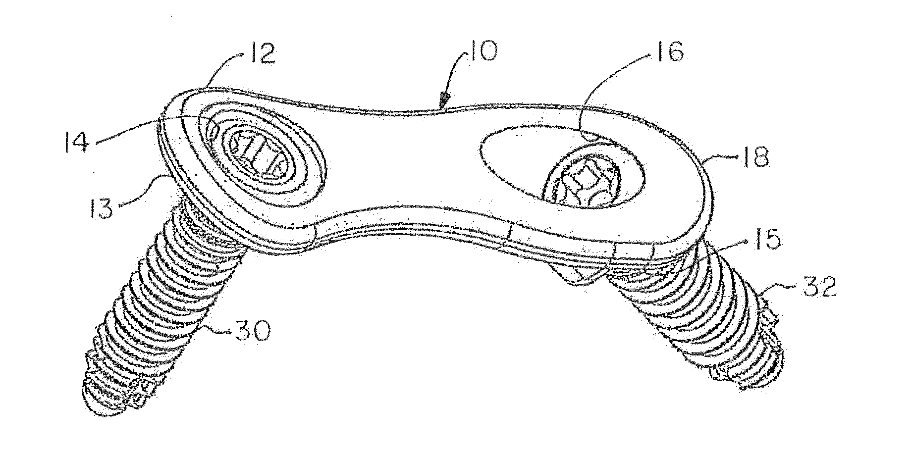
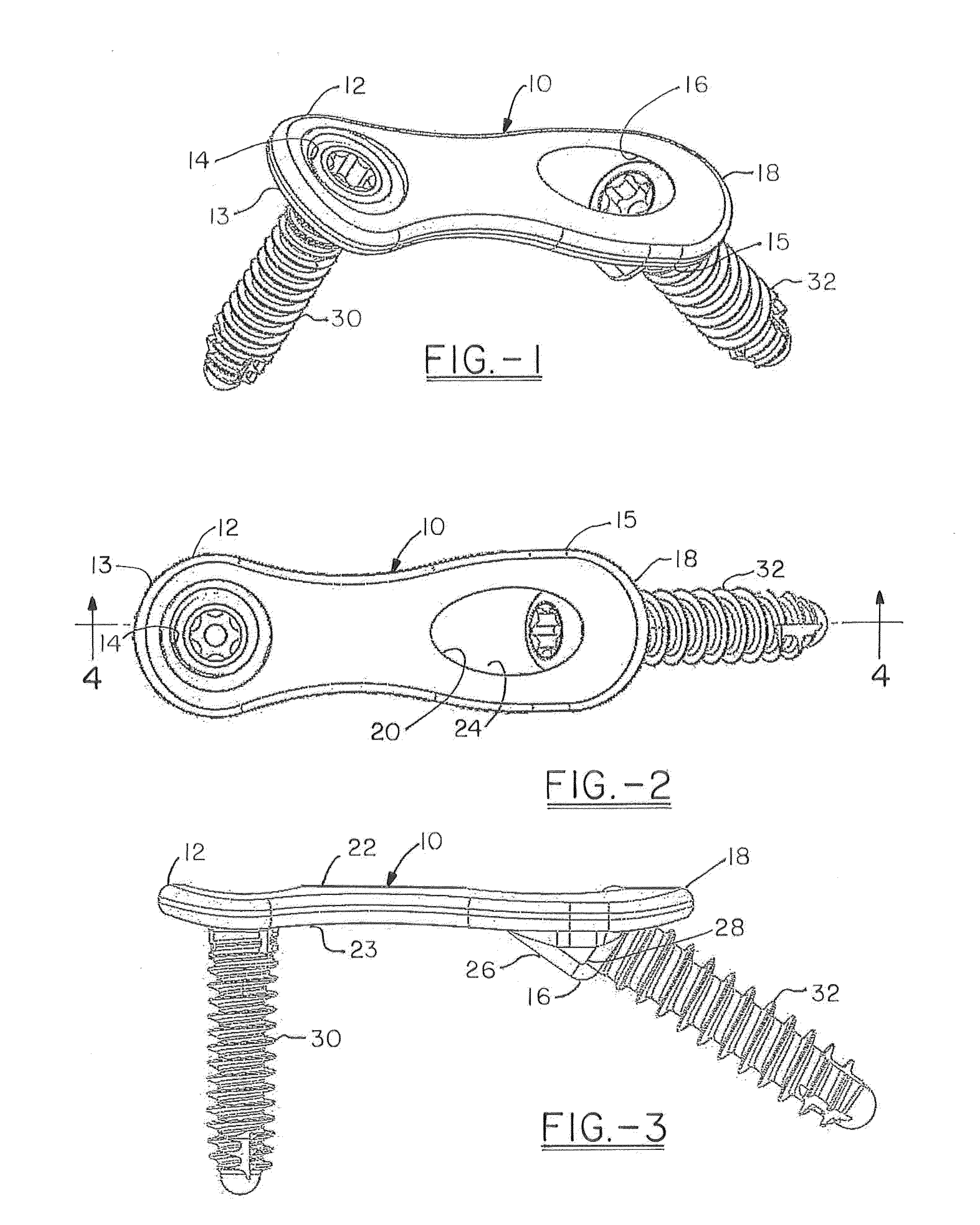
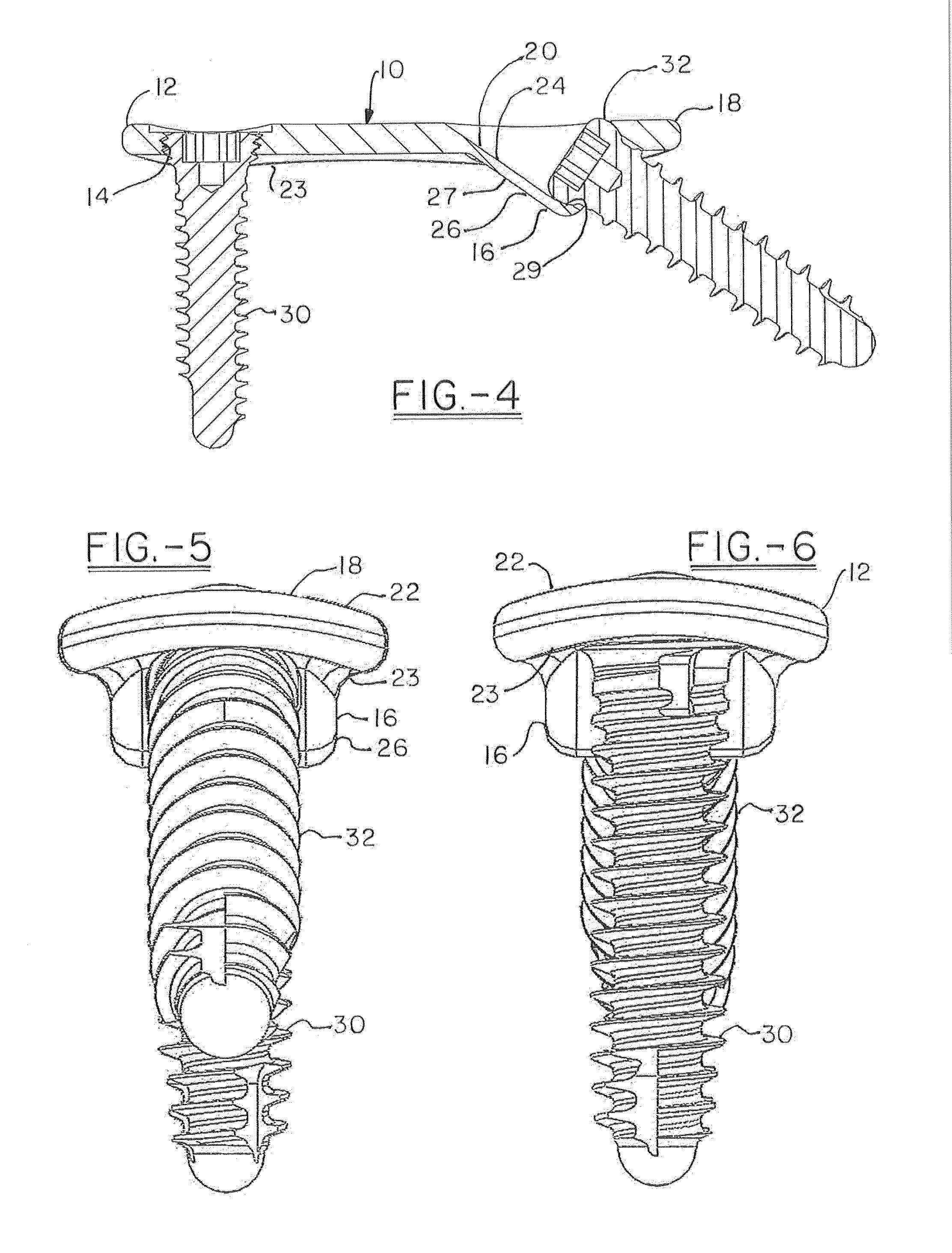
[0051]FIGS. 1-6 show the compression pocket plate of the present invention. This embodiment illustrates the compression housing of the present invention used with a universal two ended plate 10 which can be used for a variety of applications in which it is desirable to achieve compression for a relatively small area between bones or bone fragments. The plate has a first end 12 having a rounded tab 13 just large enough to form a suitable mounting for a threaded locking hole 14, which receives a threaded locking screw 30. As used herein the term “tab” suggests a projection which includes a rounded portion for example large enough to accommodate an opening for a screw hole and contiguous material which holds the rounded projection to the general plate body. The plate also has a second end 18 with an elongated tab 15 that includes a compression housing 16. The compression housing 16 includes an opening 20 in the top surface 22 of the plate. The opening 20 is ovoid, with a width that wid...

third embodiment

[0053]the plate is shown in FIGS. 17-30. In this version, the plate is intended for a bunionectomy. The plate 210 has a first end 212 having symmetrical double rounded tabs 213 (i.e. mouse ears) just large enough to form a suitable mounting for threaded locking holes 214, which receive a threaded locking screws 230. The also has a second end 218 with an elongated tab 215 that tapers and includes a sharp chamfer, suitable for insertion into bone, such as by tamping. The plate also includes a compression housing 216. The compression housing 216 includes an opening 220 in the top surface 222 of the plate. The opening 220 is ovoid, with a width that wide enough to accept the compression screw 32 that is received in the opening 220. The opening 220 angles into the top surface 222 of the plate 210 so as to form a groove 224 that accommodates and guides the screw 232 and a mating driver as the screw is screwed into the bone below the plate. On the bottom surface 223 of the plate 210 there ...

second embodiment

[0054]FIGS. 31-35 illustrate a second version of the second embodiment, i.e. the MPT plate 310, of the present invention. In this version both the first and the second ends 312,318 includes three tabs 313,315 and locking holes 314 within each tab. The plate 310 continues to have the same angles for dorsiflexion and for valgus. In the first end, in which an axis can be defined along the medial axis of the plate to the mid-line, and dividing the terminal most screw hole in half, the second tab hole forms an angle of about 25° to the long axis and the screw hole has an angle of about 21° + / −8°, preferably + / − about 5°, and most preferably about 2° to the screw axis of the terminal most hole, while the screw hole in the third tab has an angle of about 18°+ / −8°, preferably + / − about 5°, and most preferably about 2° to the screw axis of the terminal most hole, with a preferred difference of about 3°. The geometry of the opposite end of the plate mirrors the first end, with the exception t...


PUM


Abstract

An orthopedic plate has a first end including a locking screw hole that receives a locking screw and spaced from that hole is a compression housing that extends from the bone-facing side of the plate and which receives a compression screw that forms an angle of from about 10° to about 70° with a longitudinal axis of the plate. In a further embodiment, the plate also includes a second end with a chamfer for insertion of the plate into bone, and in a still further embodiment, the plate is an MTP plate.

Description

CROSS REFERENCE[0001]This Application claims the benefit of priority under 35 U.S.C. §119 of U.S. Provisional Application Ser. No. 61 / 463,323, filed on Feb. 15, 2011 and U.S. Provisional Application Ser. No. 61 / 580,680, filed on Dec. 28, 2011, herein fully incorporated by reference.FIELD OF THE INVENTION[0002]The present invention relates to an orthopedic plated which is configured to increase compression at a bone interface, in particular to stabilize bones or bone fragments relative to each other such as to cause fusion. Specific embodiments and methods of fixation are presented for fixation of the bones of the foot including, for example, stabilization of a fracture, dislocation or reconstruction of a deformity such as use in osteotomies and bunionectomies. The invention also applies to fusion procedures in other areas of the body, including the wrist or hand.BACKGROUND OF THE INVENTION[0003]The feet and the hands both include numerous bones and joints that cooperate together to ...

Claims


Application Information

Patent Timeline
IPC IPC(8): A61B17/80
CPCA61B17/8014A61B17/8095A61B17/8061
Inventor LEWIS, DEREK S.ALTENAU, ELIZABETHBENNETT, GORDONDEN HARTOG, BRYAN D.HEAVENER, JACKSON R.JOHNSON, JEFFREYKAY, DAVID B.HOCKETT, BRIAN
Owner ORTHOHELIX SURGICAL DESIGNS
Why Eureka
Try Eureka