Load control system

a control system and load technology, applied in secondary cell servicing/maintenance, emergency power supply arrangements, instruments, etc., can solve the problems of large capacity backup power supply and increase the cost of the system

Inactive Publication Date: 2012-08-16
PANASONIC INTELLECTUAL PROPERTY MANAGEMENT CO LTD
View PDF10 Cites 21 Cited by
  • Summary
  • Abstract
  • Description
  • Claims
  • Application Information

AI Technical Summary

Benefits of technology

[0006]In view of the above, the present invention provides a low-cost load control system which

Problems solved by technology

Therefore, the power is backed up only for a short period of time, which results in requirement of a large capacity backup power supply.
In such load control system, since the load devices need to hav

Method used


Image

  • Load control system
  • Load control system
  • Load control system

Examples


Embodiment Construction

[0025]The embodiments of the present invention will be described with reference to the accompanying drawings which form a part hereof. Throughout this specification and the drawings, like reference numerals designate like parts having substantially identical functions, and redundant description thereof will be omitted.

[0026]Hereinafter, the embodiments of the present invention will be described with reference to the drawings which form a part hereof. Although an example in which a load control system of the present invention is applied to a detached house will be described in the following embodiments, the load control system can be applied to an apartment, a business building or the like.

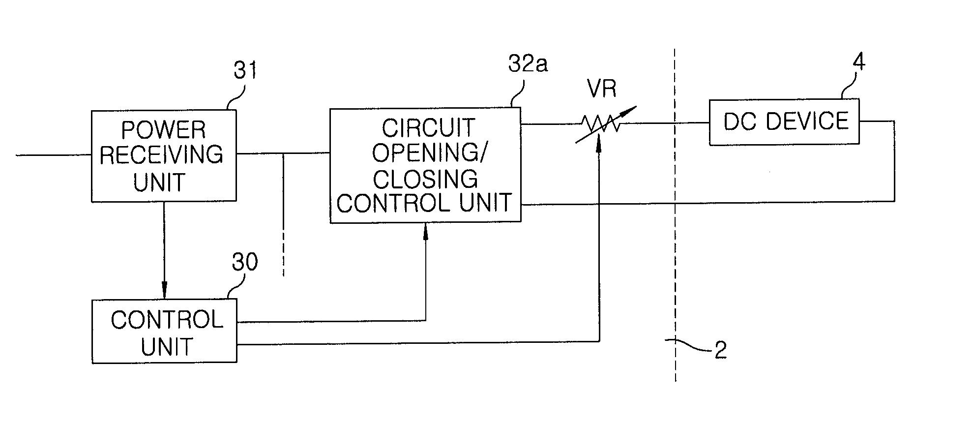
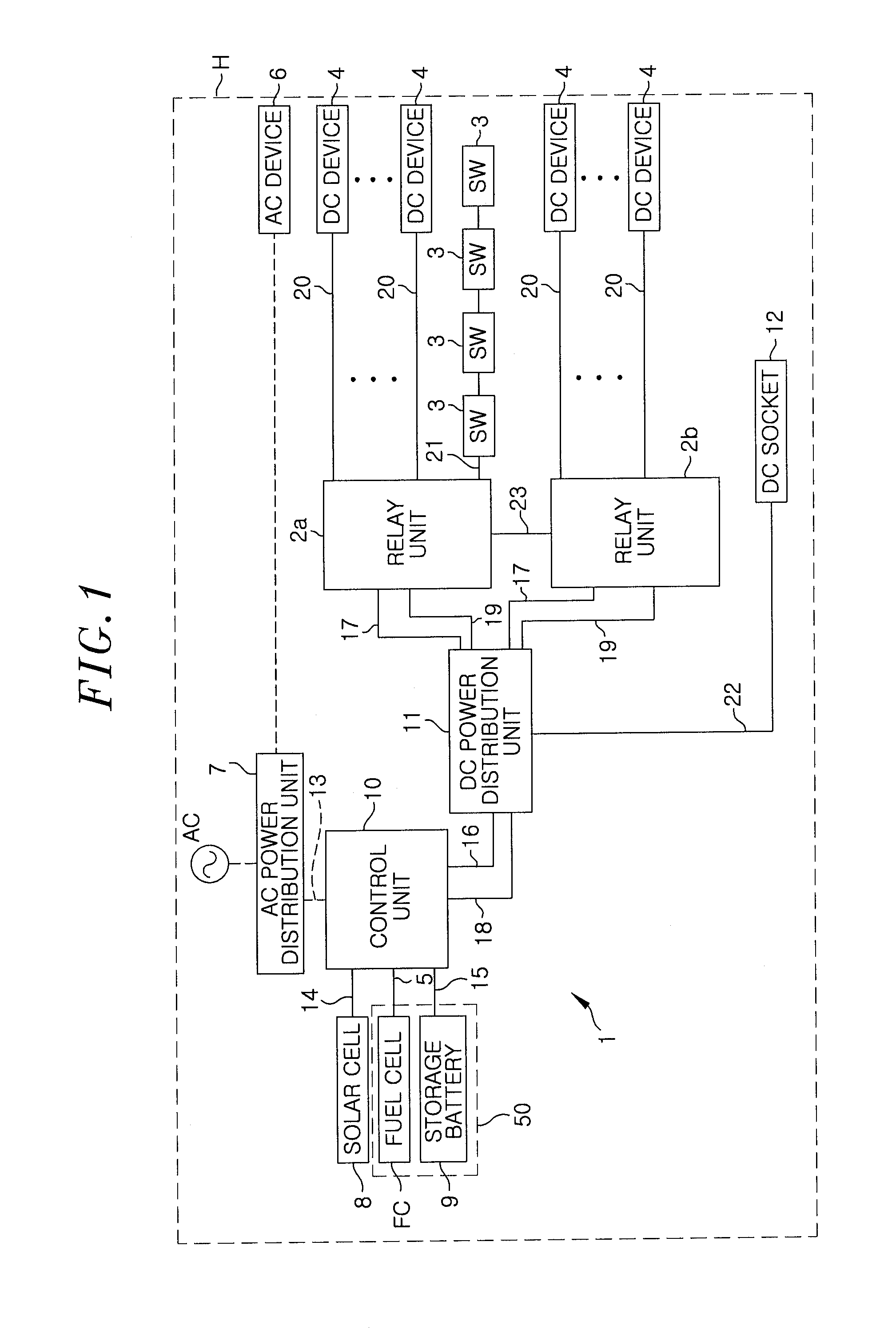
[0027]As shown in FIG. 1, a house H has therein DC devices 4 (e.g., an LED lighting device, a ventilation fan, an air conditioner, audio / video equipments and the like) as load devices which are operated by a DC power supplied thereto, and a load control system 1 for turning on / off the DC power feed...


PUM


Abstract

A load control system includes: a power supply control unit for controlling a power feeding to multiple load devices; and a backup power supply unit for supplying backup power during a power failure. During a power failure, the power supply control unit supplies the power from the backup power supply unit only to a part of load devices selected among the load devices, and the load devices are devoid of communications function for communicating with the power supply control unit.

Description

FIELD OF THE INVENTION[0001]The present invention relates to a load control system.BACKGROUND OF THE INVENTION[0002]Conventionally, there has been provided a load control system for operating only a preset load by supplying a power from a backup power supply to the corresponding load during a power failure (see, e.g., Japanese Patent Laid-open Publication No. 2009-148009).[0003]The load control system described in Patent Document 1 supplies a DC power from a main power supply to DC devices connected to DC power supply lines and also supplies a backup power from a backup power supply provided in addition to the main power supply to the DC devices via the DC power supply lines during a power failure in the main power supply. Thus, the DC devices can operate for a predetermined period of time even during the power failure in the main power supply.[0004]In the above-described load control system, when the power is supplied from the backup power supply to all the DC devices connected to ...

Claims


Application Information

Patent Timeline
IPC IPC(8): G06F1/30
CPCH01M10/44H01M16/006H02J9/061H02J13/0003H02J2001/004Y02B90/14Y02B90/228Y04S20/12Y04S20/18H02J1/14Y02B90/222H02J2300/30Y02B90/20Y04S10/12Y02E40/70Y02E60/50Y02E60/10H02J1/08Y02B90/10Y04S20/00
Inventor HIRATA, SATOSHIMATSUURA, SHUJIFUJITA, YUJI
Owner PANASONIC INTELLECTUAL PROPERTY MANAGEMENT CO LTD
Why Eureka
Try Eureka