Arrangement and method for characterizing magnetic systems

a magnetic system and arrangement method technology, applied in the field of arrangement and method for characterizing magnetic systems, can solve the problems of inability to simulate systems involving relative permeabilities other than unity, inability to calculate faster analytical models, and inability to simulate systems with complex mathematical operations. , to achieve the effect of easy evaluation and analysis

Active Publication Date: 2012-08-16
MAGCAM
View PDF4 Cites 36 Cited by
  • Summary
  • Abstract
  • Description
  • Claims
  • Application Information

AI Technical Summary

Benefits of technology

[0018]The present invention relates to a method of considerably speeding up the above general method of fitting calculated or simulated data to measurement data. The method thereby makes use of precalculated simulation data which need to be calculated only once for a particular magnetic system configuration. During the optimization procedure, the precalculated data is treated using fast algorithms such as, but not limited to, linear combinations and interpolation schemes in order to obtain a best fit to the measured data. The input parameters of the model are thus optimized without the need for resimulating the complete system at every iter

Problems solved by technology

Analytical models can calculate faster than FEM models, but are restricted in the type of magnetic system

Method used


Image

  • Arrangement and method for characterizing magnetic systems
  • Arrangement and method for characterizing magnetic systems
  • Arrangement and method for characterizing magnetic systems

Examples


examples

[0055]Below are some examples of applying the present invention to permanent magnets.

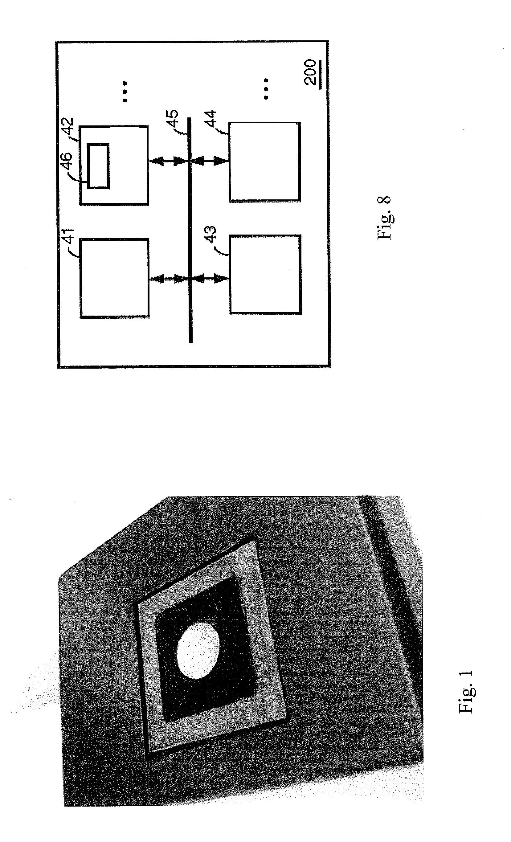
[0056]FIG. 1: Cylindrical magnet with axial magnetization placed on a magnetic field camera measurement device with 128×128 Hall magnetic field sensors on an area of 13 mm*13 mm (=16384 sensors). The complete array is measured in less than one second.

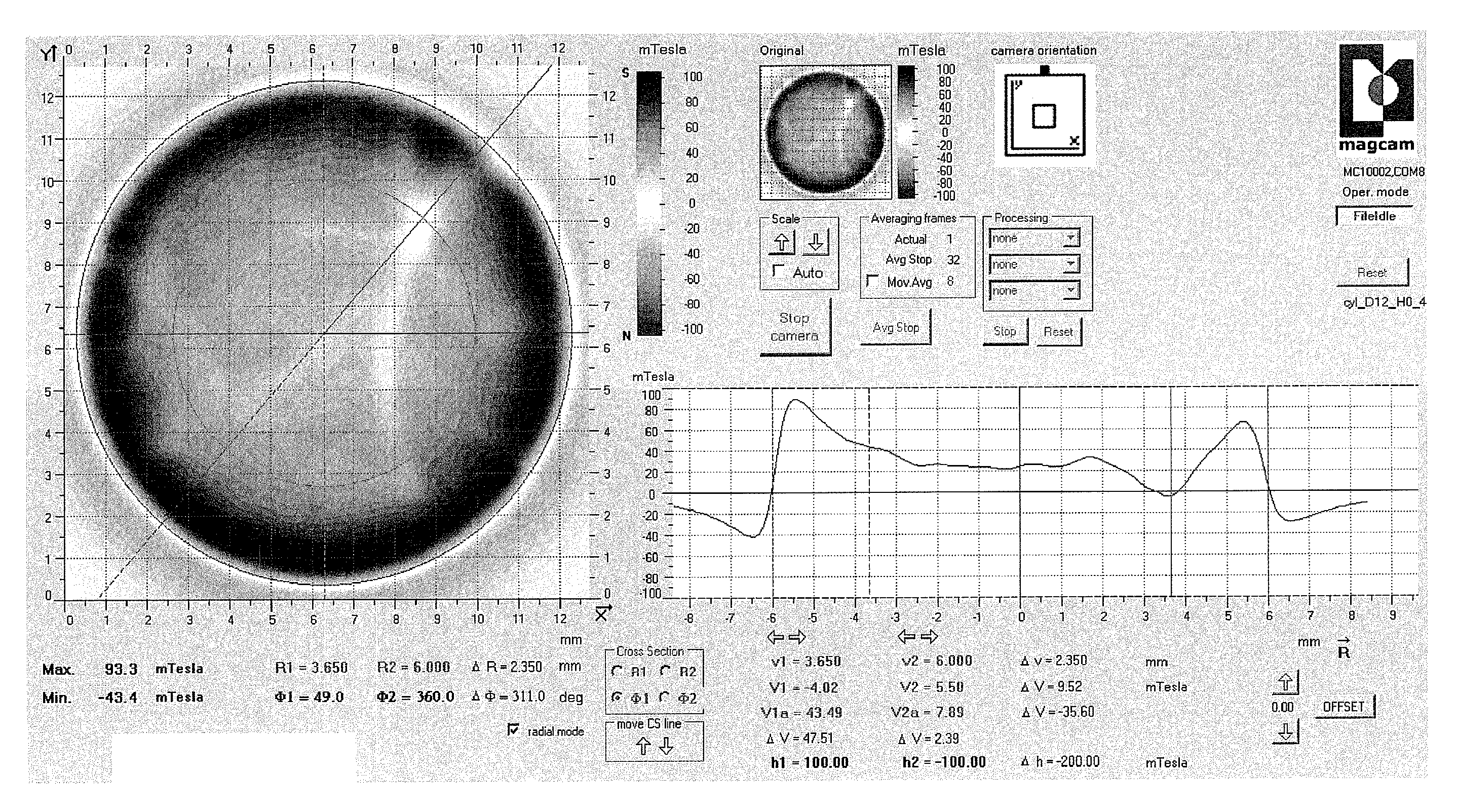
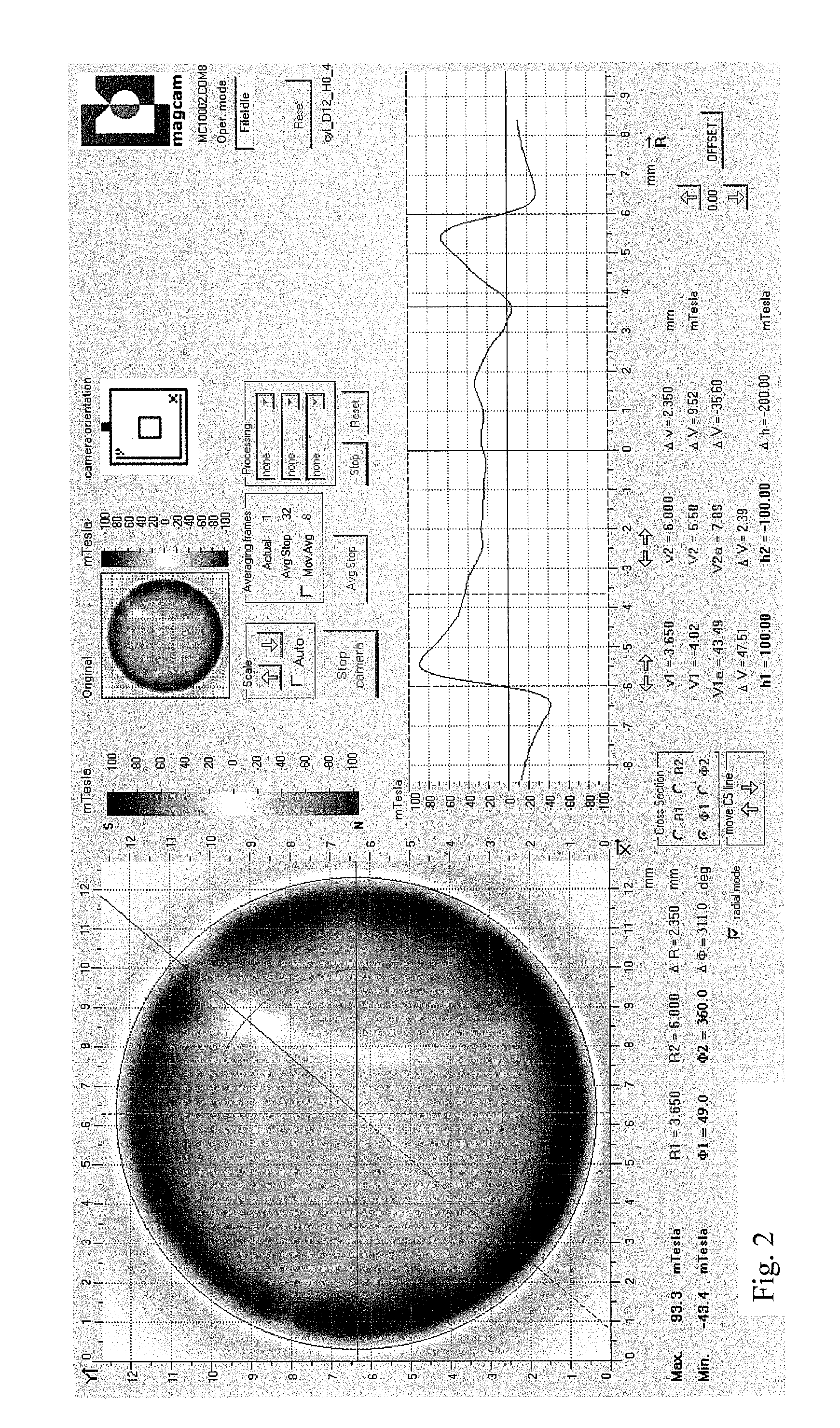
[0057]FIG. 2: Measured magnetic field distribution of the magnet shown in FIG. 1. The measured magnetic field component is the Bz component, perpendicular to the magnetic field camera sensor.

[0058]FIG. 3: Results of an optimization procedure according to the present invention for the magnet of FIG. 1 and FIG. 2. The measurement data is loaded using the ‘Load data’ button. For the analysis, the magnet geometry is selected in the drop-down box on the right (‘cylinder’). The first column of the larger table (‘Initial value’) shows the initial values (starting values) for the optimization procedure. Based on these initial values, precalculated simulated mag...


PUM


Abstract

The present invention relates to a new method for characterizing magnets, magnetic assemblies (combinations of magnets) and magnetic materials. In what follows, these will be called under the common term ‘magnetic systems’. The method is based on obtaining quantitative properties of the magnetic system by combining magnetic field measurement data and theoretical modeling or simulation data. The input parameters of the theoretical model are optimized using an optimization method in order to obtain a best fit to the measured data. In this method, the present invention involves precalculating magnetic field distributions prior to the optimization execution in order to considerably speed up the process. Combining this advanced data processing with fast magnetic field mapping using e.g. a magnetic field camera, allows real-time measurement and data analysis of magnetic systems for applications in e.g. quality control of such magnetic systems.

Description

TECHNICAL FIELD OF THE INVENTION[0001]The current invention is situated in the field of magnetic measurements and inspection, research, development and quality control of magnets, magnetic assemblies, magnetic materials (all of which called ‘magnetic systems’) and products involving such magnetic systems. More specifically, the present invention relates to a method to extract information from a two-dimensional mapping of the magnetic field of a magnetic system. This magnetic mapping can, in one embodiment, be obtained from a ‘magnetic field camera’ system, which is able to record high resolution 2D magnetic field maps at high speeds, which makes it possible to apply the process in e.g. fast quality control of magnetic systems. The extraction of information from the magnetic field map is done by comparing the measurement data to simulated or calculated data from a magnetic system, based on a magnetic model. The input parameters of the magnetic model are varied and optimized as to obt...

Claims


Application Information

Patent Timeline
IPC IPC(8): G06F19/00G06F17/10G01R33/02
CPCG01R33/0064G01R33/10G01R33/0094
Inventor VERVAEKE, KOEN JOZEF THEO
Owner MAGCAM
Why Eureka
Try Eureka