Tubular building structure with hingedly connected platform segment

a technology of platform segment and building structure, applied in the direction of sustainable buildings, building repairs, cranes, etc., can solve the problems of difficult, expensive or impossible transportation along public roads

Inactive Publication Date: 2012-08-23
ANDRESEN TOWERS
View PDF20 Cites 25 Cited by
  • Summary
  • Abstract
  • Description
  • Claims
  • Application Information

AI Technical Summary

Benefits of technology

[0004]An object of the present invention is to provide a method of erec...

Problems solved by technology

However, in the recent years the height of such building structures and, consequently, the diameters of the tube s...

Method used


Image

  • Tubular building structure with hingedly connected platform segment
  • Tubular building structure with hingedly connected platform segment
  • Tubular building structure with hingedly connected platform segment

Examples


Embodiment Construction

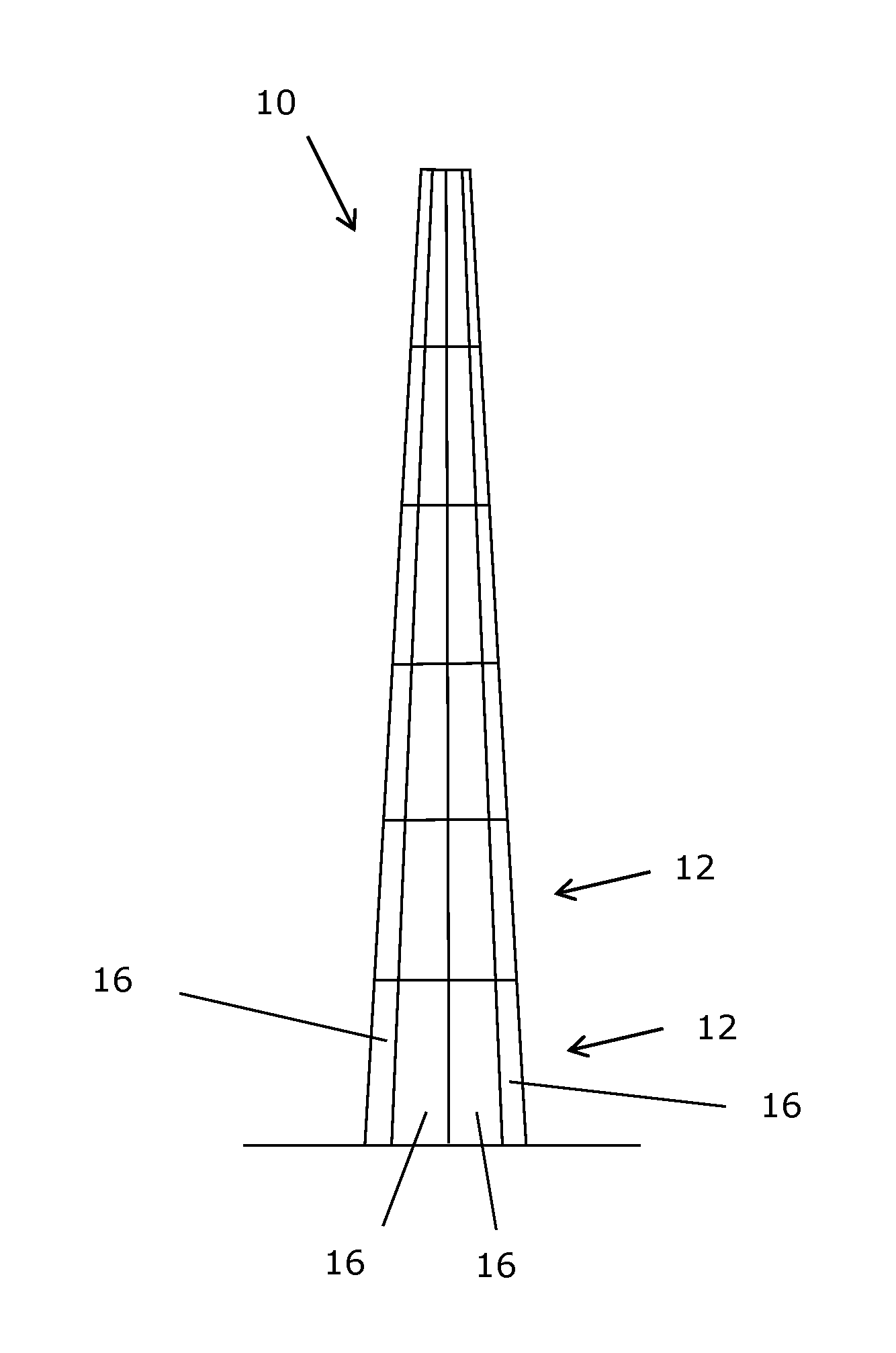
[0041]FIG. 1 shows schematically the principle of having a tubular building structure or tower 10 formed by six superposed tube sections 12 each being formed by of a number of interconnected axially extending tube segments 16. The tower 1035 shown in FIG. 1 has an upwardly decreasing cross section. However, the cross section may also be substantially constant or upwardly increasing depending e.g. on the actual use of the tower 10. The tower 10 typically comprises a lower base (not shown) used to ensure stable fastening / anchoring of the tower the ground. This base and possibly also the lower tube section 12 may be made conventionally or in any other suitable way.

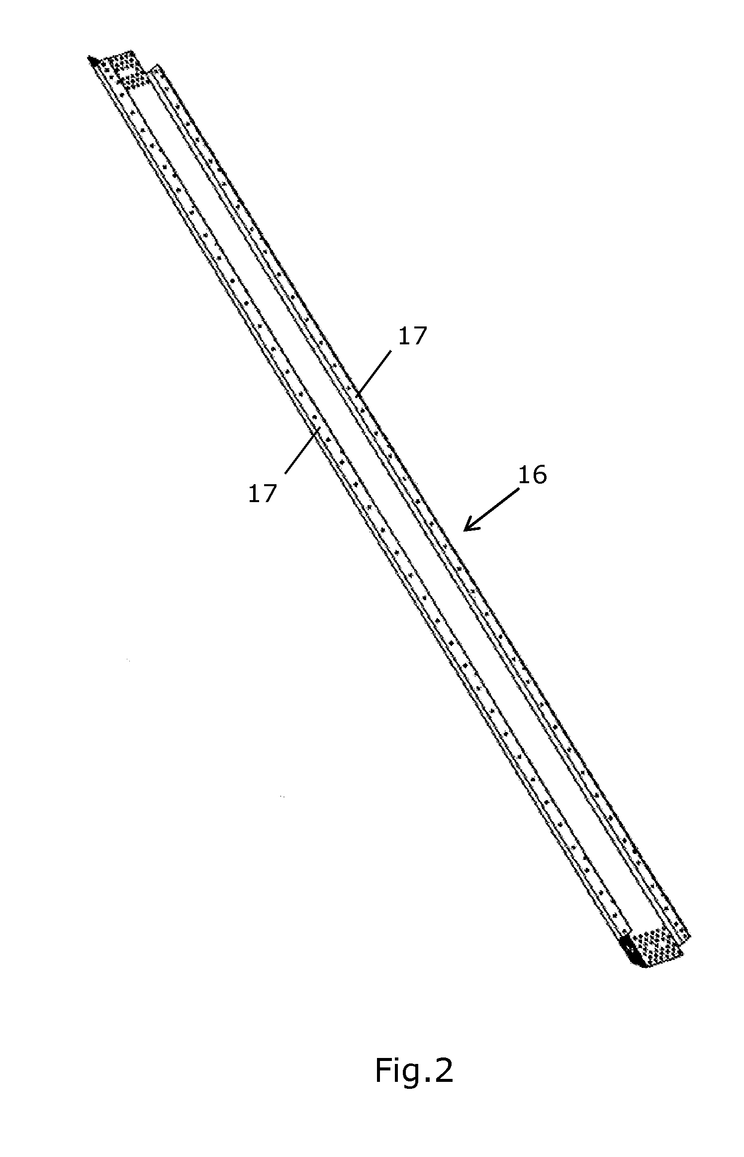
[0042]FIG. 2 shows an example of a tube segment 16 to be used in a method according to the present invention. The illustrated tube segment 16 is made by bending a metal plate, so that a polygonal cross section of the tower 10 is obtained. An alternative is to use rolled plates whereby a circular cross section can be obtained....


PUM


Abstract

The present invention relates to a tubular building structure or tower 10 comprising superposed tube sections 12. At least some of the tube sections 12 are provided with platform segments 28 that are hinge-connected and foldable from a collapsed position in which they are positioned close to the tube sections 12 to a position of use in which they extend radially inwardly into the tubular building structure 10 in the mounted position of the tube sections 12. In particular the invention relates to a tube segment 16 adapted to be interconnected with other tube segments 16 to 17 form a tubular building structure or tower 10 comprising superposed tube sections 12, each tube section being formed by interconnected axially extending tube segments 16. The tube segment 6 is provided with a platform 28 segment 28 that is hinge-connected and foldable from a collapsed position in which it is positioned close to the tube segment 16 to 1 a position of use in which it extends radially inwardly into the tubular building structure 10 in the mounted position of the tube segments 16. The tube segment 6 may comprise flanges 17 along each side of opposite longitudinal sides of the tube segment 16 for interconnection with other tube segments 16 via registering holes in the flanges 17. Furthermore, the platform segment 28 may be hinge-20 connected to such flanges 17. The invention further relates to a method of erecting a tubular building structure 10 comprising such tube segments 16.

Description

FIELD OF THE INVENTION[0001]The present invention relates to tubular building structures or towers, such as a telecommunication tower, a wind turbine tower or the like. In particular it relates to a tubular building structure comprising a platform located inside the tubular building structure.BACKGROUND OF THE INVENTION[0002]Conventionally, such tubular building structures have been made from tube sections of rolled steel plate arranged on top of each other. However, in the recent years the height of such building structures and, consequently, the diameters of the tube sections have been ever increasing so that they are difficult and expensive or impossible to transport along public roads. In an attempt to solve this problem, it has been proposed to divide each tube section into a number of longitudinally extending tube segments which may be interconnected so as to form the tube sections at the building site.[0003]Tubular building structures or towers, including those mentioned abov...

Claims


Application Information

Patent Timeline
IPC IPC(8): E04H12/18E04H12/00E04G21/14
CPCE04H7/22E04H12/08Y02B10/30E04H12/34Y02E10/728E04H12/085E04G3/243E04G5/08E04G7/30
Inventor KRYGER, ARNERYHOLL, LARS
Owner ANDRESEN TOWERS
Why Eureka
Try Eureka